Water-cooled brake hub and waterway system thereof

A brake grain, water-cooled technology, applied in the field of brake cooling devices, can solve the problems of non-concentricity of the sealing ring and the water storage cover, poor sealing effect of the sealing ring, lack of effective support for the water storage cover, etc., and achieves simple structure and improved use. Longevity, the effect of ensuring concentricity

Active Publication Date: 2015-11-18
李涛 +1
View PDF9 Cites 2 Cited by
  • Summary
  • Abstract
  • Description
  • Claims
  • Application Information

AI Technical Summary

Problems solved by technology

Due to the low rotation speed of the tires, the blades on the water storage cover cannot effectively circulate the cooling water, which limits the cooling effect of the device
In addition, because the water storage cover is fixed by the tire steel ring, the water storage cover will rotate together with the wheel hub, and it is difficult to form an effective connection between the water storage cover and the water inlet pipe and outlet pipe. Moreover, due to the lack of effective support for the water storage cover, it is difficult to It is easy to cause the sealing ring and the water storage cover to be misaligned, resulting in poor sealing effect of the sealing ring or aggravated wear of the sealing ring, which eventually leads to coolant leakage

Method used


Image

  • Water-cooled brake hub and waterway system thereof
  • Water-cooled brake hub and waterway system thereof
  • Water-cooled brake hub and waterway system thereof

Examples


Embodiment 1

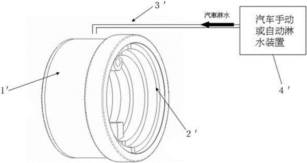
[0038] Such as figure 1 , 2 , 3, 4, and 5, the water cover 1 is installed outside the brake hub body 2, and two bearings are installed between the water cover 1 and the brake hub body 2, namely the first bearing 3 and the second bearing 4. The first bearing 3 is installed on the small end of the brake hub body 2 as the first bearing member, the brake hub body 2 is connected with the inner ring of the first bearing 3 , and the water cover 1 is connected with the outer ring of the first bearing 3 . The second bearing 4 is installed on the big end of the brake hub body 2 as the second bearing part, the brake hub body 2 is connected with the inner ring of the second bearing 4 , and the water cover 1 is connected with the outer ring of the second bearing 4 .

[0039] A first sealing ring 5 as a first sealing member and a second sealing ring 6 as a second sealing member are installed between the first bearing 3 and the second bearing 4 . If the first bearing 3 and the second bear...

Embodiment 2

[0044] Figure 6 , 7 Shown is the waterway system for constructing the cooling cycle using the brake hub of Embodiment 1. In the present embodiment 2, the temperature control system of the waterway system consists of a data processing control board, a water pump, a temperature sensor, a condenser, a water tank, a first solenoid valve 13, a second solenoid valve 14, a booster pump, a first filter device and a second filter. Wherein, the water tank is used as a liquid storage tank, and a certain amount of water can be stored in advance as a cooling liquid. The water pump draws the water in the water tank and sends it to the downstream condenser. The condenser acts as a condensing device to lower the water temperature. A filter, that is, the first filter, is generally installed between the water pump and the condenser to filter impurities in the water entering the condenser. As a data processing module, the data processing control board is electrically connected with the tem...

Embodiment 3

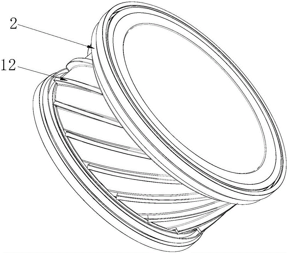
[0048] The difference between this embodiment 3 and embodiment 1 is that, as Figure 8 As shown, in the third embodiment, a plurality of cooling fins 12 are formed on the brake hub body 2, and these cooling fins 12 are arranged side by side.


PUM


Abstract

Th invention discloses a water-cooled brake hub. The water-cooled brake hub comprises a water shade and a brake hub body; the water shade is installed outside the brake hub body, and a cooling liquid circulation space is formed between the water shade and the brake hub body; the water-cooled brake hub further comprises a first bearing component and a second bearing component which can rotate relative to the brake hub body, and the first bearing component and the second bearing component are located between the water shade and the brake hub body and connected with the water shade; a first sealing element and a second sealing element are arranged between the water shade and the brake hub body, the first sealing element and the second sealing element are located between the first bearing component and the second bearing component or outside the first bearing component and the second bearing component; the water shade is further provided with a water inlet and a water outlet which are located between the first sealing element and the second sealing element. The water-cooled brake hub is simple in structure, the bearings are adopted to fixedly connect the water shade with the brake hub, abrasion of a seal ring is greatly reduced, and the service life of the seal ring is prolonged. The invention further discloses a waterway system which is established by means of the water-cooled brake hub.

Description

technical field [0001] The invention relates to a brake cooling device, in particular to a water-cooled brake hub and its waterway system. Background technique [0002] When the car is running, it often encounters a long downhill road, and the driver will use the brakes continuously. Car braking generally uses brake pads and brake hub friction to form a huge friction force, thereby achieving the car braking effect. However, the frequent braking of the car during driving will cause the brake hub and brake pad to generate a lot of heat due to intense friction. If the heat cannot be dissipated in a timely and effective manner, the temperature of the brake hub and brake pads will increase. [0003] High temperature is the most important factor for the brake failure of the car. When the temperature of the brake system of the car is higher than 85°C, the braking effect of the brake system begins to weaken. At this time, the temperature of the brake system is inversely proportion...

Claims


Application Information

Patent Timeline
Patent Type & Authority Applications(China)
IPC IPC(8): B60T5/00
CPCB60T5/00
Inventor 李涛黎申斌
Owner 李涛
Why Eureka
Try Eureka