Pole climbing robot based on spring telescopic mechanism
A telescopic mechanism and robot technology, applied in the field of pole-climbing robots, can solve the problems of small bearing capacity, large influence of the surrounding environment, poor structural stability, etc., and achieve the effects of large bearing capacity and diversified functional applications.
- Summary
- Abstract
- Description
- Claims
- Application Information
AI Technical Summary
Problems solved by technology
Method used
Image

Examples
specific Embodiment approach 1
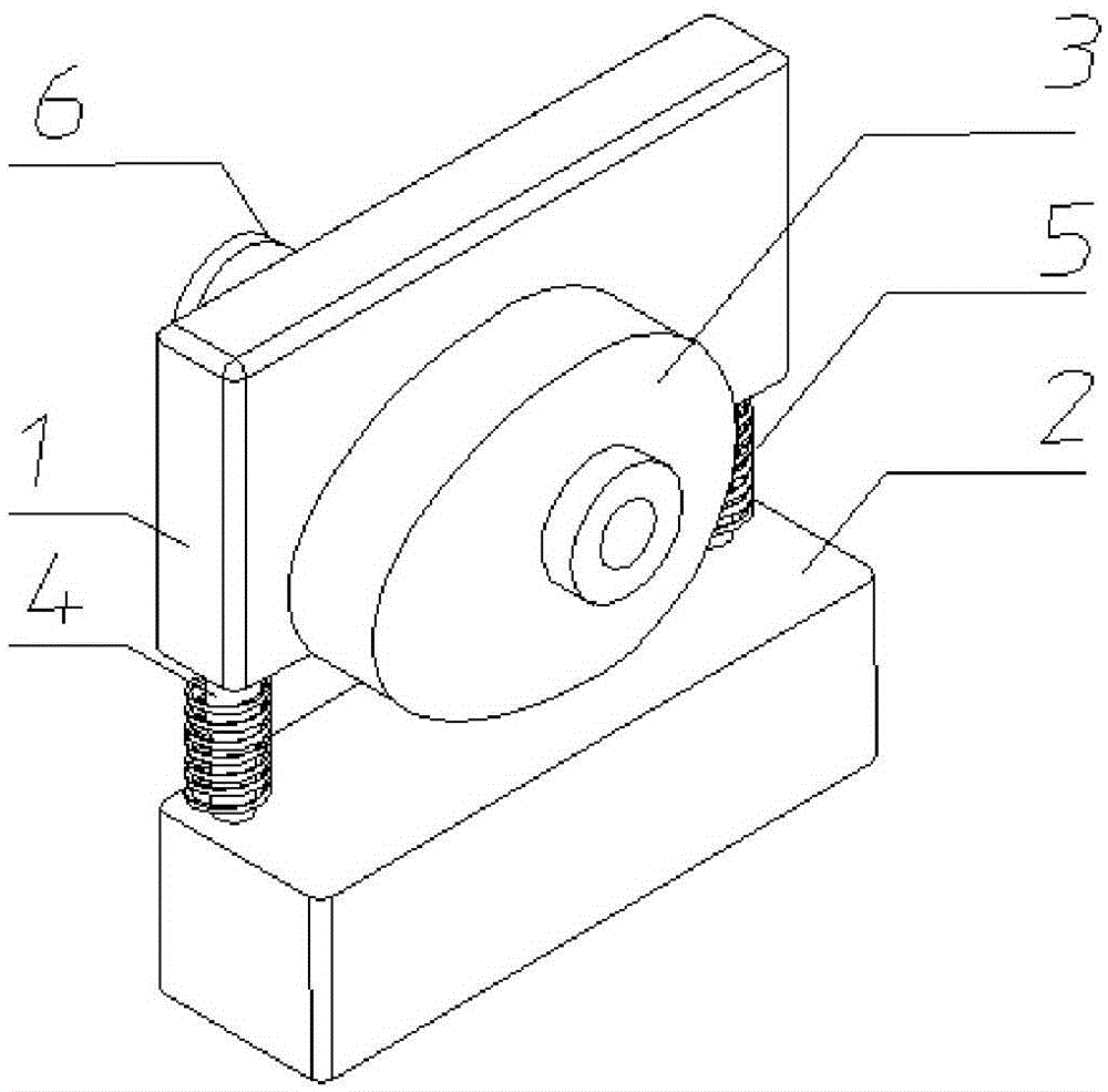
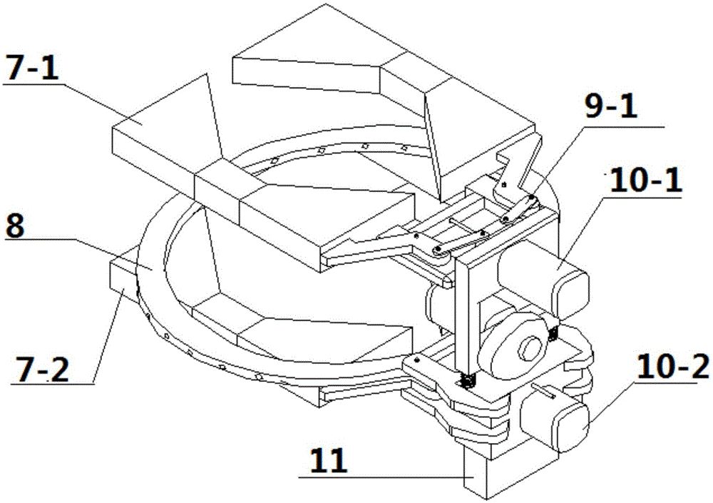
[0021] Specific implementation mode one: combine Figure 1 to Figure 5 Describe this embodiment, this embodiment includes a spring telescopic mechanism, a first manipulator 7-1, a second manipulator 7-2, a functional assembly 8, a first crank linkage mechanism 9-1, and a second crank linkage mechanism 9-2 , the third crank-link mechanism 9-3, the first pole climbing motor 10-1, the second pole climbing motor 10-2 and the accumulator 11,
[0022] Storage battery 11 is installed in the lower end of spring telescopic mechanism, and the first manipulator 7-1 and the second manipulator 7-2 are arranged in parallel up and down, and respectively through the first crank linkage mechanism 9-1 and the 3rd crank linkage mechanism 9-3 and The spring telescopic mechanism is connected, the first pole climbing motor 10-1 and the second pole climbing motor 10-2 are respectively connected with the first manipulator 7-1 and the second manipulator 7-2, and the functional assembly 8 is installed ...
specific Embodiment approach 2
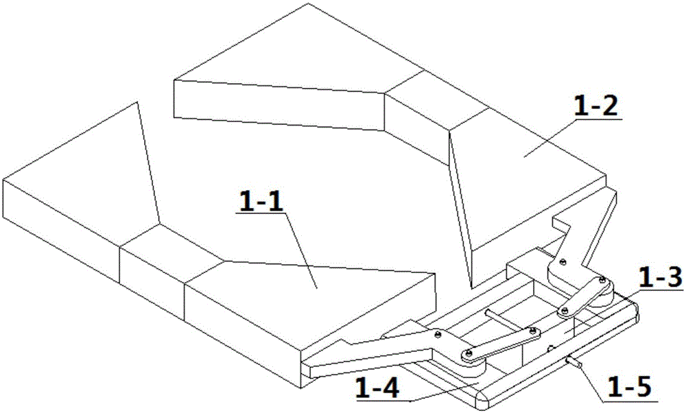
[0024] Specific implementation mode two: combination figure 2 and image 3 Describe this embodiment, the structure of the first manipulator 7-1 of this embodiment and the second manipulator 7-2 are the same, the first manipulator 7-1 comprises left hand claw 1-1, right hand claw 1-2, walking slider 1-3 , connector 1-4 and lead screw 1-5,
[0025] Left-hand claw 1-1 and right-hand claw 1-2 are arranged oppositely, and the inner sides of left-hand claw 1-1 and right-hand claw 1-2 are provided with inner pits, and the same side of left-hand claw 1-1 and right-hand claw 1-2 Connector 1-4 is connected on the outer wall, travel slider 1-3 is installed in connector 1-4, leading screw 1-5 passes travel slider 1-3 and is installed on connector 1-4, the first One end of the crank link mechanism 9-1 is connected with the same side outer wall of the left hand claw 1-1 and the right hand claw 1-2, and the other end of the first crank link mechanism 9-1 is connected with the walking slid...
specific Embodiment approach 3
[0026] Specific implementation mode three: combination Figure 5 Describe this embodiment, the functional assembly 8 of this embodiment comprises left tool frame 4-1, right tool frame 4-2, work slide block 4-3, work lead screw 4-4 and work connecting frame 4-5, left tool Frame 4-1 and right tool rack 4-2 are semicircular arc tool racks, and the same side of left tool rack 4-1 and right tool rack 4-2 is connected by working connecting frame 4-5, and working slider 4-3 Installed in the working connecting frame 4-5, the working screw 4-4 is installed on the working connecting frame 4-5 through the working slider 4-3, and one end of the second crank linkage mechanism 9-2 is installed on the working slider 4-3, the other end of the second crank-link mechanism 9-2 is connected with the left tool rack 4-1 and the right tool rack 4-2. In this way, the threaded connection is used between the working slider and the working screw, and the rotation of the screw is manually driven, and th...
PUM
 Abstract
Description
Claims
Application Information
 - R&D
- Intellectual Property
- Life Sciences
- Materials
- Tech Scout
- Unparalleled Data Quality
- Higher Quality Content
- 60% Fewer Hallucinations
Browse by: Latest US Patents, China's latest patents, Technical Efficacy Thesaurus, Application Domain, Technology Topic, Popular Technical Reports.
© 2025 PatSnap. All rights reserved.Legal|Privacy policy|Modern Slavery Act Transparency Statement|Sitemap|About US| Contact US: help@patsnap.com