Constant-power control device and pressure variable control method thereof

A technology of constant power control and flow control valves, which is applied in the direction of fluid pressure actuators, servo motor components, mechanical equipment, etc., and can solve the problems of inability to stabilize the movement speed of actuators, failure to ensure stable oil pressure, damage to mechanical device components, etc. problems, to achieve the effect of low vibration and noise, simple structure and good sealing performance

Inactive Publication Date: 2015-11-18
SUZHOU SABO IND DESIGN
View PDF8 Cites 2 Cited by
  • Summary
  • Abstract
  • Description
  • Claims
  • Application Information

AI Technical Summary

Problems solved by technology

At present, there are control valves that use the principle that the hydraulic pressure acting on the spool is equal to the spring force, but when the load pressure of the actuator of the mechanical device changes greatly, the existing flow pressure control valve usually uses What is more important is a single-stage pressure control valve. Its pressure regulation method cannot ensure the stability of the oil pressure in the mechanical equipment, that is, it cannot effectively stabilize the movement speed of the actuator, and when the oil pressure reaches a large peak , will cause mechanical device components to suffer huge pressure shocks and cause damage

Method used


Image

  • Constant-power control device and pressure variable control method thereof
  • Constant-power control device and pressure variable control method thereof

Examples


Embodiment Construction

[0024] In order to make the technical means, creative features, goals and effects achieved by the present invention easy to understand, the present invention will be further described below in conjunction with specific illustrations.

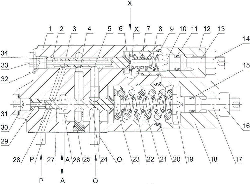
[0025] Such as figure 1 As shown, the present invention includes: valve body 1, first blind hole 2, first left working port 3, first middle working port 4, first right working port 5, first left spring seat 6, first large spring 7 , the first small spring 8, the first O-ring 9, the first right spring seat 10, the second O-ring 11, the first valve cover 12, the first pressure regulating bolt 13, the first pressure regulating nut 14, the fourth O-ring 15, second pressure regulating nut 16, second pressure regulating bolt 17, second valve cover 18, second right spring seat 19, third sealing ring 20, second large spring 21, second small spring 22, Second left spring seat 23, second right working port 24, adjustable two-way throttle valve 25, second...


PUM


Abstract

The invention relates to a constant-power control device which comprises a valve body. A flow control valve and a pressure control valve are arranged in the valve body. The flow control valve comprises a first valve element, a first spring cavity and a primary spring. The pressure control valve comprises a second valve element, a second spring cavity and a secondary spring. According to the constant-power control device, the two control valves are arranged to carry out hierarchical control over oil pressure; the primary flow control valve controls the magnitude of the flow mainly through flow distribution, and the secondary pressure control valve controls the magnitude of pressure mainly through oil-return unloading; the problems that the braking torque and the oil temperature rapidly rise due to continuous rising of pressure after out of control of pressure are effectively solved, and use is reliable.

Description

technical field [0001] The invention relates to a control device, in particular to a constant power control device and a pressure variable control method thereof. Background technique [0002] The flow pressure control valve is a component that plays the role of constant pressure relief in the hydraulic system. By controlling the pressure and flow of the liquid flow to meet the requirements of the actuator, it plays the role of pressure stabilization, system unloading and safety protection. At present, there are control valves that use the principle that the hydraulic pressure acting on the spool is equal to the spring force, but when the load pressure of the actuator of the mechanical device changes greatly, the existing flow pressure control valve usually uses What is more important is the single-stage pressure control valve. Its pressure regulation method cannot ensure the stability of the oil pressure in the mechanical equipment, that is, it cannot effectively stabilize ...

Claims


Application Information

Patent Timeline
IPC IPC(8): F15B13/02
CPCF15B13/023
Inventor 丁会张苏陈力航
Owner SUZHOU SABO IND DESIGN
Why Eureka
Try Eureka