
Vale blade sealing structure and air valve

A technology of valve blades and sealing structures, which is applied in the direction of valve lifts, valve devices, engine components, etc., can solve problems such as difficulty in guaranteeing straightness and flatness machining accuracy, inability to completely block fire or smoke, and gaps in the closing of valve blades, etc. Achieve good acid and alkali corrosion resistance, light weight and good thermal stability

Active Publication Date: 2015-11-18
ZHONGHANG DAJI ENG PRODS SHENZHEN
View PDF6 Cites 8 Cited by
  • Summary
  • Abstract
  • Description
  • Claims
  • Application Information

AI Technical Summary

Problems solved by technology

[0002] At present, the air volume leakage of air volume control valves, fire dampers, smoke exhaust dampers, smoke exhaust valves and other air valves used in central air conditioning or other ventilation systems cannot meet the national standard during use, and there will be gaps when the valve blades are closed. , the amount of leakage cannot be controlled
Especially for large-sized valve blades, it is difficult to guarantee the machining accuracy of straightness and flatness after forming, and the air leakage at the overlapping parts between the valve blades will be greater
More seriously, when a fire or other emergency occurs, it is necessary to close the air valve in the ventilation system, but the air leakage between the valve blades cannot completely block the fire or smoke, which poses a huge threat to personal and property safety. could have more serious consequences

Method used


Image

  • Vale blade sealing structure and air valve
  • Vale blade sealing structure and air valve
  • Vale blade sealing structure and air valve

Examples


Embodiment Construction

[0019] The present invention will be further described below in conjunction with the accompanying drawings and specific embodiments.

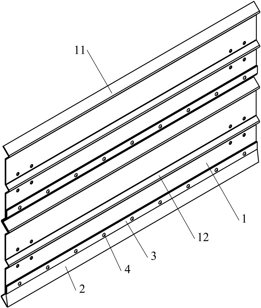
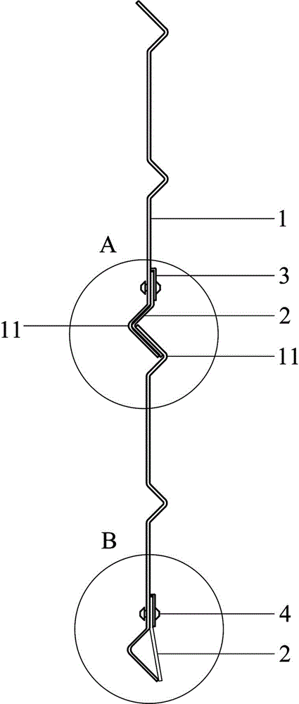
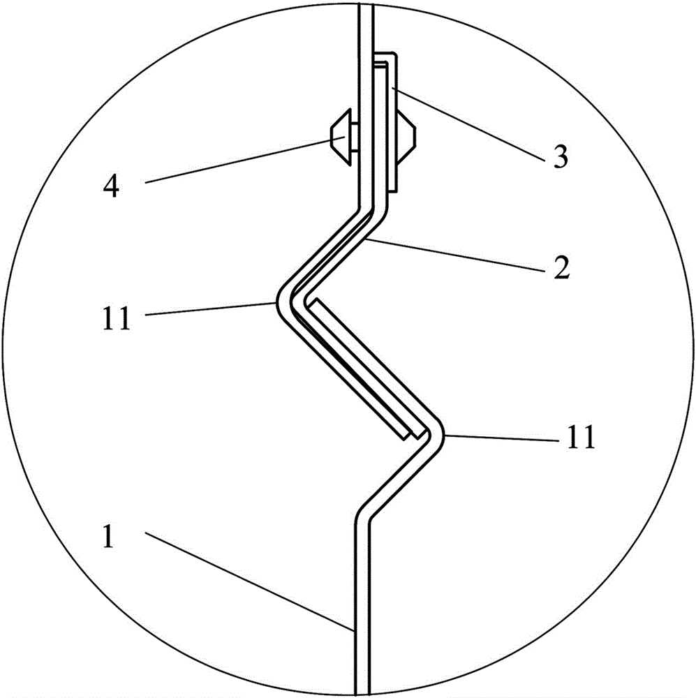
[0020] See figure 1 and figure 2 , a valve blade sealing structure designed in a preferred embodiment of the present invention, including: valve blade 1 and sealing strip 2, the upper and lower ends of a plurality of valve blades 1 overlap each other to form a plane, which is used as a damper valve, and sealing strip 2 By using the bead 3 and the rivet 4 to be fixedly installed on one end of the valve blade 1, it plays the role of making up the connection gap between the valve blades.

[0021] See image 3 and Figure 4 The upper and lower ends of the valve blade 1 are bent and extended to form an overlapping portion 11. The overlapping portion 11 is composed of an obliquely protruding starting folding surface and a reversely folded final folding surface. The two adjacent valve blades 1 The bending directions of the overlapping parts 11 ar...


PUM


Abstract

The invention discloses a valve blade sealing structure and an air valve. The valve blade sealing structure comprises valve blades. The upper ends and the lower ends of the valve blades are provided with lap joint parts. The directions of the lap joint parts of every two adjacent valve blades are opposite. Each lap joint part is composed of a folding start face obliquely extending out and a folding stop face reversely folded back. A flexible sealing strip is arranged on one side of one end of the lap joint. A pressing strip is arranged at the upper end of the sealing strip. The pressing strip and the sealing strip are fixed to the valve blades through rivets in an inserting manner. The lower end of the sealing strip is squeezed by and attached to the folding stop faces of the two corresponding adjacent lap joint parts. The valve blade sealing structure is simple and convenient to install; and when the air valve is closed, the flexible sealing strip is deformed under the acting force of the lap joint parts of the valve blades so as to adaptively fill the connecting gaps between the lap joint parts of the valve blades, and therefore the leakage amount of air valves such as an air volume regulating valve, a fire valve, a smoke exhausting fire valve and a smoke exhausting valve is controlled to be reduced as much as possible.

Description

technical field [0001] The invention relates to the field of air valves and accessories thereof, in particular to a valve blade sealing structure and an air valve using the valve blade sealing structure. Background technique [0002] At present, the air volume leakage of air volume control valves, fire dampers, smoke exhaust dampers, smoke exhaust valves and other air valves used in central air conditioning or other ventilation systems cannot meet the national standard during use, and there will be gaps when the valve blades are closed. , the amount of leakage cannot be controlled. Especially for large-sized valve blades, it is difficult to guarantee the processing accuracy of straightness and flatness after forming, and the air leakage at the overlapping parts between the valve blades will be greater. More seriously, when a fire or other emergency occurs, the air valve in the ventilation system needs to be closed tightly, but the air leakage between the valve blades cannot...

Claims


Application Information

Patent Timeline
Patent Type & Authority Applications(China)
IPC IPC(8): F16K1/226F16K1/228
CPCF16K1/2261F16K1/228
Inventor 唐战郭海军
Owner ZHONGHANG DAJI ENG PRODS SHENZHEN
Learn More