Intelligent metering pry and metering method thereof

A metering method and technology of metering skid, applied in pipeline systems, mechanical equipment, gas/liquid distribution and storage, etc., can solve problems such as difficulty in meter reading, improvement of unfavorable processes, reduction of energy consumption, and large production-to-sales ratio of gas companies. , to achieve the effect of being conducive to management and maintenance, reducing subsequent operating costs, and reducing the cost of manual meter reading

Active Publication Date: 2015-11-18
SHANGHAI FIORENTINI GAS EQUIP
View PDF5 Cites 5 Cited by
  • Summary
  • Abstract
  • Description
  • Claims
  • Application Information

AI Technical Summary

Problems solved by technology

[0007] 1) The internal pipeline is complicated and there are many leakage points;
[0008] 2) The number of flow meters is large, the installation environment is harsh, and meter reading is difficult;
[0009] 3) There are many types and brands of flowmeters, and the flowmeters are constantly replaced with new ones from the beginning of operation, which makes maintenance difficult. Even the production of flowmeters of some brands and types has stopped, and the spare parts cannot keep up with the problem;
[0010] 4) The production status of continuous gas supply makes these flowmeters unable to be calibrated on time and increases the measurement error;
[0011] 5) Some flowmeters have no temperature and pressure compensation, and the measurement error is large;
[0012] 6) All measurement signals are not collected and summarized, and there is no data, which is not conducive to subsequent data analysis, and is not conducive to process improvement and energy consumption reduction;
[0013] 7) The reliability of the entire metering system is low; resulting in a large ratio of production and sales of gas companies, resulting in a huge deficit

Method used


Image

  • Intelligent metering pry and metering method thereof

Examples


Embodiment Construction

[0033] The present invention will be further described below in conjunction with the accompanying drawings and specific embodiments.

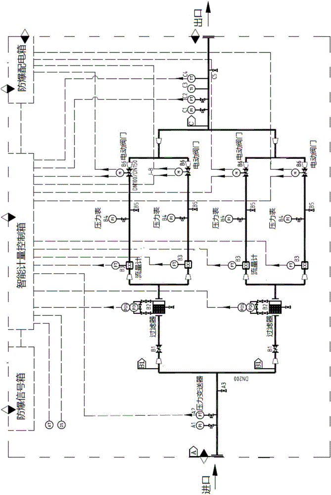
[0034] see figure 1 , an intelligent metering skid, including an air intake main pipe, the air intake main pipe communicates with at least two air intake branch pipes, each air intake branch pipe is provided with a filter B2, and the filter B2 filters the upstream air and divides it into two Metering branch, each metering branch is equipped with a flow meter B3 and an electric cut-off valve B6 behind the flow meter; the two metering branches are combined into one outlet branch pipe, and each outlet branch pipe is combined into one outlet main pipe; intelligent metering control is also included The intelligent metering control box is connected with the signal of the filter B2, the flow meter B3, and the electric cut-off valve B6, and the flow meter B3 transmits the flow data signal to the intelligent metering control box, and the intelligent met...


PUM


Abstract

The invention relates to an intelligent metering pry. An air inlet manifold is communicated with at least two air inlet branch tubes. Each air inlet branch tube is provided with a filter. Air is completely filtered by each filter and then goes into two metering branches. Each metering branch is provided with a flowmeter and an electric partition valve located behind the flowmeter. Two corresponding metering branches are combined into one air outlet branch tube. All the air outlet branch tubes are combined into one air outlet manifold. The intelligent metering pry further comprises an intelligent metering control box. The intelligent metering control box is in signal connection with the filters, the flowmeters and the electric partition valves. The flowmeters transmit flow data signals to the intelligent metering control box, and the intelligent metering control box chooses to open or close the electric partition valves on the metering branches according to the flow in actual operation, so that the appropriate measuring range of total flow is selected to achieve metering. Power lines are connected to an explosion-proof distribution box, and the explosion-proof distribution box supplies electricity to the intelligent metering control box and the electric partition valves. The intelligent metering pry is arranged in a gas company. Intelligent metering pries correspond to gas using units one to one.

Description

technical field [0001] The invention relates to an intelligent metering skid and a metering method thereof, in order to satisfy industrial, commercial and public building users in gas transmission and distribution to perform accurate metering in a large flow range, and belongs to the technical field of gas transmission and distribution metering. Background technique [0002] At present, industrial and commercial users, such as ceramic kiln users, heat treatment furnace users of mechanical parts, natural gas heater users, commercial residential users, etc., have a lot of gas-consuming equipment, and the gas consumption of a single combustion equipment is small, but the total gas consumption The amount is very large; and according to the nature of the gas used, according to the different process procedures, the temperature achieved by the gas combustion and the time for holding the heat are also different; the frequency of use and working conditions of multiple production lines...

Claims


Application Information

Patent Timeline
Patent Type & Authority Applications(China)
IPC IPC(8): F17D1/02F17D3/01F17D3/18
Inventor 张飞飞潘良高宇廖戌郎石丽丽施汉龙
Owner SHANGHAI FIORENTINI GAS EQUIP
Why Eureka
Try Eureka