

Electric motor or generator
A technology for generators and motors, applied in motors, electric components, electric vehicles, etc., can solve problems such as the reduction of motor efficiency and power generation capacity, and achieve the effect of optimizing cooling
- Summary
- Abstract
- Description
- Claims
- Application Information
AI Technical Summary
Problems solved by technology
Method used
Image

Examples
Embodiment Construction
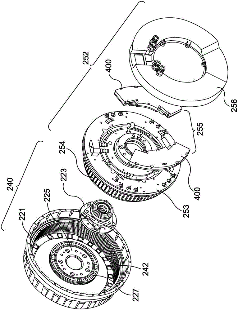
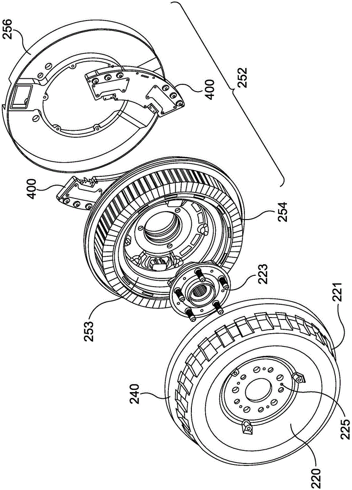
[0023] figure 1 and figure 2 An electric motor assembly comprising an electric motor with cooling arrangement according to the present invention is shown, wherein the electric motor assembly includes built-in electronics and is configured to be used as an in-wheel motor or an in-wheel motor housed in a wheel. However, the present invention may be incorporated in any form of electric motor. The electric motor can also be configured as a generator.
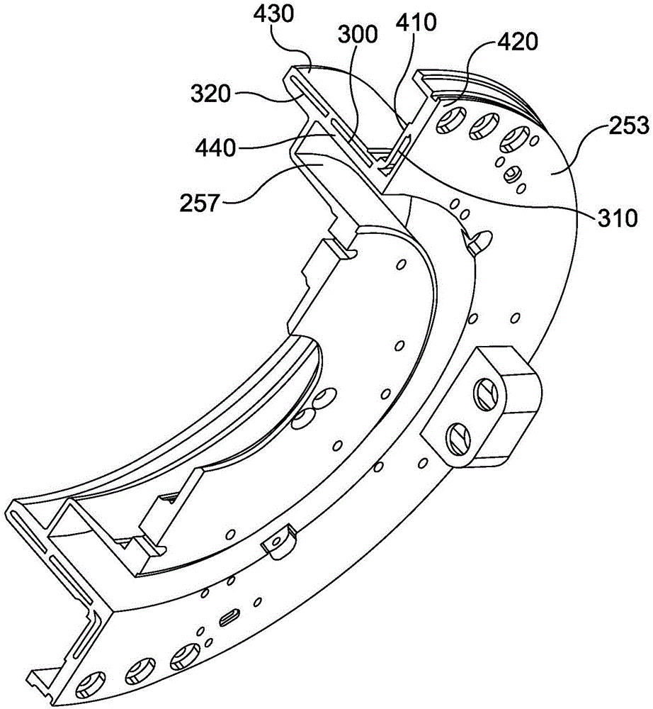
[0024] For the purposes of this example, if figure 1 and figure 2 As shown, the in-wheel motor includes a stator assembly 252 and a rotor assembly 240 . The stator assembly 252 includes a heat sink 253 with cooling channels, a plurality of coils 254, an electronics module 255 mounted on the rear of the stator for driving the coils, and a stator mounted in a recess 257 formed on the rear of the stator. on the capacitor (not shown). In a preferred embodiment, the capacitor is a ring capacitor element.
[0025] Coils 254 are f...
PUM
 Abstract
Description
Claims
Application Information