

Multifunctional robot wrist with replaceable end actuator
An end-effector and multi-functional technology, applied in the field of robot wrists, can solve the problems of high production cost, inconvenient use, inability to drive multiple end-effectors with the same wrist, etc., and achieves simple structure, convenient protection, and favorable control. effect of operation
- Summary
- Abstract
- Description
- Claims
- Application Information
AI Technical Summary
Problems solved by technology
Method used
Image

Examples
specific Embodiment approach 1
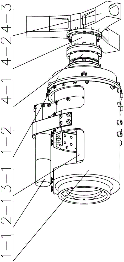
[0008] Specific implementation mode one: combine Figure 1-Figure 7 Describe this embodiment, a multifunctional robot wrist with a replaceable end effector, which includes an outer power output mechanism 1, a middle layer locking and releasing mechanism 2, an inner layer power output mechanism 3 and a tool mechanism 4, and an outer power output mechanism 4. The output mechanism 1 and the middle layer locking and releasing mechanism 2 are set on the inner layer power output mechanism 3 sequentially from outside to inside, and the tool mechanism 4 is installed on the power output end of the outer layer power output mechanism 1 and the middle layer locking and releasing mechanism 2 On the power take-off end and the power take-off end of inner layer power take-off mechanism 3.
specific Embodiment approach 2
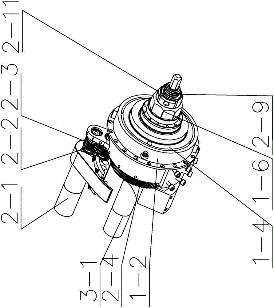
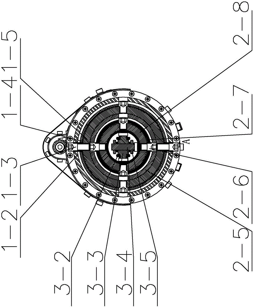
[0009] Specific implementation mode two: combination Figure 1-Figure 5 Describe this embodiment, a multifunctional robot wrist with replaceable end effector in this embodiment, the outer power output mechanism 1 includes a drive mechanism support 1-1, an outer cross shaft outer ring 1-2, an outer cross Shaft inner ring 1-4, outer cross shaft 1-5, octagonal tool wrench 1-6 and four outer layer mechanism cylindrical head screws 1-3, and the octagonal tool wrench 1-6 is processed with multiple grooves, and the outer The cross shaft outer ring 1-2, the outer cross shaft inner ring 1-4 and the outer cross shaft 1-5 are sequentially set from the outside to the inside, and the four outer mechanism cylindrical head screws 1-3 are along the circumference of the outer cross shaft 1-5 The directions are uniformly arranged on the outer cross shaft outer ring 1-2, and each outer mechanism cylindrical head screw 1-3 passes through the outer cross shaft outer ring 1-2 and the outer cross sh...
specific Embodiment approach 3
[0010] Specific implementation mode three: combination Figure 1-Figure 6 Describe this embodiment, a multifunctional robot wrist with replaceable end effector in this embodiment, the middle layer locking and releasing mechanism 2 includes a first servo motor assembly 2-1, a gear with a first gear shaft 2-2. Gear 2-3 with second gear shaft, third gear 2-4, middle cross shaft outer ring 2-5, middle cross shaft inner ring 2-7, middle cross shaft 2-8, tool lock Tightening 'T' shaped screw rod 2-9, tool locking 'T' shaped nut 2-10, four release mechanism cylindrical head screws 2-6 and multiple steel balls 2-11, tool locking 'T' shaped nut 2- 10 is processed with a plurality of protruding ribs corresponding to multiple grooves on the octagonal tool wrench 1-6, and arc-shaped grooves are processed between two adjacent protruding ribs. The output shaft of the first servo motor assembly 2-1 One end of the gear shaft is connected with the gear 2-2 gear shaft with the first gear shaft...
PUM
 Abstract
Description
Claims
Application Information