A model stage of a centrifugal compressor

A technology of centrifugal compressor, model

Active Publication Date: 2017-05-24
嘉兴芸诗娇电子商务有限公司
View PDF7 Cites 0 Cited by
  • Summary
  • Abstract
  • Description
  • Claims
  • Application Information

AI Technical Summary

Problems solved by technology

However, due to the complex structure and aerodynamic design of the flow parts, the internal flow field is relatively complicated. If the structure and aerodynamic design are unreasonable, the performance and efficiency of the whole machine will be reduced. Therefore, how to effectively flow through the centrifugal compressor In-depth research on the internal flow of the components can provide some guidance for the design and optimization of the compressor flow parts, so as to further improve the efficiency of the centrifugal compressor has become a very important issue today

Method used


Image

  • A model stage of a centrifugal compressor
  • A model stage of a centrifugal compressor
  • A model stage of a centrifugal compressor

Examples


Embodiment Construction

[0039] The present invention will be further described below in conjunction with the accompanying drawings and embodiments.

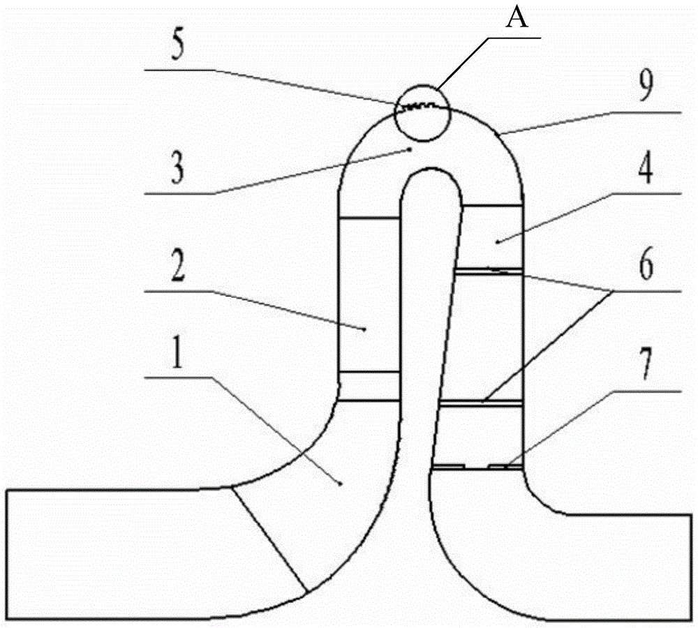
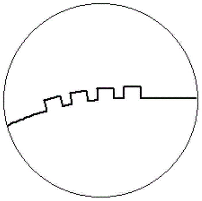
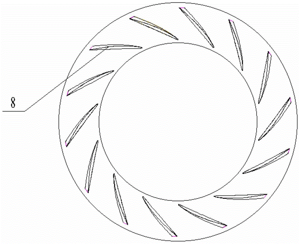
[0040] like Figure 1a and 2 As shown, a model stage of a centrifugal compressor includes an impeller 1 , a vaned diffuser 2 , a bend 3 and a reflux device 4 . The vane diffuser 2 is arranged at the outlet of the impeller 1; the diffuser vane 8 of the vane diffuser 2 is a curved vane, that is, the side of the diffuser vane 8 that is close to the diffuser wheel cover is bent to form a steady outlet. flow sheet; the trailing edge line of the outlet stabilizing sheet and the axial angle of the vane diffuser 2 are 3°, so that the outlet angle of the diffuser blade 8 is enlarged by 3° compared with the original blade; the outlet stabilizing sheet can make The originally unstable air flow on the wheel cover side of the vane diffuser 2 becomes more uniform, reducing the flow loss of gas inside the vane diffuser 2 and improving the overall operating efficiency...


PUM


Abstract

The invention discloses a centrifugal compressor model stage. my country's centrifugal compressor technology still needs to be continuously improved, so as to enhance the stability of compressor operation and improve the efficiency of compressor operation. The present invention comprises impeller, vane diffuser, bend and reflux device; vane diffuser is arranged at the outlet of impeller; The side of the wheel cover is bent to form an outlet stabilizing plate; the outlet of the vane diffuser communicates with the bend; the outer wall of the bend is provided with an annular groove; There is a drag reducing groove, and the reflux blade has a rectangular groove at the outlet of the blade. The present invention improves the diffuser, bend and reflux structure of the existing centrifugal compressor model stage to ensure that the operating efficiency of the centrifugal compressor model stage is improved and the stability of operation is enhanced; the energy gradient function in the diffuser is proposed The formula for calculating the value.

Description

technical field [0001] The invention belongs to the technical field of ventilation equipment, and in particular relates to a model stage of a centrifugal compressor. Background technique [0002] In my country, gas transportation and gas compression machinery are collectively referred to as fans. Commonly referred to as fans include ventilators, blowers, compressors and Roots blowers. Fans are classified according to their internal air flow direction, and can be mainly divided into three types: axial flow, centrifugal and mixed flow (diagonal flow). [0003] Centrifugal compressor is a kind of fan, which plays an important role in the national economy. As an energy conversion device, it mainly drives the movement of the gas in the flow channel of the impeller through the rotation of the impeller, and converts the mechanical energy of the prime mover into the energy of the gas. Due to its high pressure, wide range of stable working conditions, simple structure, and easy ma...

Claims


Application Information

Patent Timeline
Patent Type & Authority Patents(China)
IPC IPC(8): F04D29/44F04D29/30F04D29/00
Inventor 窦华书张滨炜魏义坤陈小平
Owner 嘉兴芸诗娇电子商务有限公司
Why Eureka
Try Eureka