
A high-resolution absolute phase demodulation method for fiber-optic sagnac interferometer sensors

An absolute phase, high-resolution technology, applied in the direction of instruments, measuring devices, etc., can solve the problems of low resolution, small measurement dynamic range, measurement range limited by the spectral width of the light source, etc., to achieve high resolution and large measurement range. Effect

Active Publication Date: 2017-07-25
BEIHANG UNIV
View PDF10 Cites 0 Cited by
  • Summary
  • Abstract
  • Description
  • Claims
  • Application Information

AI Technical Summary

Problems solved by technology

In recent years, many studies have adopted this kind of frequency demodulation-based scheme for sensing measurement, which solved the problem that the measurement range is limited by the spectral width of the light source, and realized the measurement of a large dynamic range, but there is a problem of low resolution.
In summary, although the peak wavelength tracking method has a high measurement resolution, the measurement dynamic range is small; the frequency demodulation method has a large measurement dynamic range, but the resolution is low

Method used


Image

  • A high-resolution absolute phase demodulation method for fiber-optic sagnac interferometer sensors
  • A high-resolution absolute phase demodulation method for fiber-optic sagnac interferometer sensors
  • A high-resolution absolute phase demodulation method for fiber-optic sagnac interferometer sensors

Examples


Embodiment Construction

[0036] The content of the present invention will be further described below in conjunction with the accompanying drawings and specific embodiments.

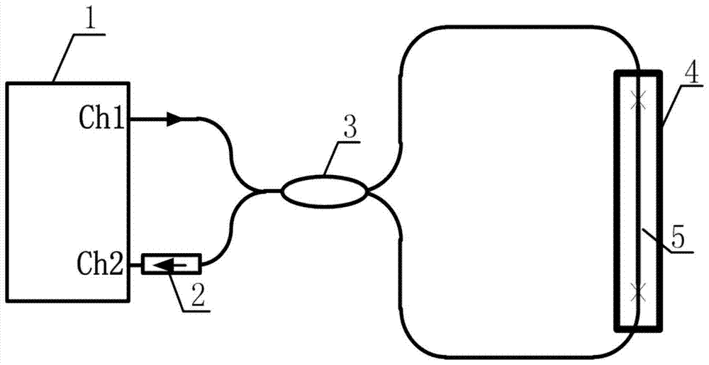
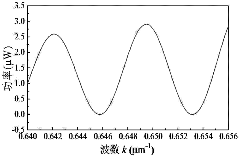
[0037] figure 1 It is a structural schematic diagram of an example of an optical fiber Sagnac interferometer temperature sensor of the present invention. Build up experimental system according to this structure, the demodulation method of the present invention is verified, see Figure 2-4 ; where experiment one verified the high-resolution characteristics of the present invention, see Figure 5 , experiment two verified the large dynamic measurement range of the present invention, see Figure 6 .

[0038] Such as figure 1 Shown: the broad-spectrum light emitted from the Ch1 channel of the spectrum demodulator 1 passes through the 2×2 single-mode coupler 3 and is divided into two paths, which are respectively transmitted around the optical fiber ring in the clockwise and counterclockwise directions, and are transmitted in the ...


PUM


Abstract

The invention discloses a high-resolution absolute phase demodulation method for a fiber Sagnac interferometer sensor. Output spectrum data of the fiber Sagnac interferometer sensor is input. First of all, abscissas of the spectrum data is converted from a wavelength to a wave number, linear coordinates are taken as ordinates, and an output interference spectrum form of the fiber Sagnac interferometer sensor is converted into a standard cosine function spectrum form; then by use of fast Fourier transform (FFT), a feature frequency of the cosine function spectrum form is extracted, and an interference order reflecting an interference spectrum period feature is calculated; data in an area nearby the feature frequency is extracted for inverse Fourier transform (IFFT), and a relative phase is calculated; and through combination with the interference order and the relative phase, a total phase is calculated so that absolute measurement of a polarization nonreciprocal phase shift or an optical path difference (OPD) is realized. According to the invention, a frequency demodulation technology and a relative phase demodulation technology are combined, and at the same time, the method provided by the invention has the advantages of large measuring scope and high resolution.

Description

technical field [0001] The invention belongs to the technical field of optical fiber sensing and relates to a high-resolution absolute phase demodulation method for optical fiber Sagnac interferometer sensors. Background technique [0002] A common fiber optic Sagnac interferometer is formed by connecting a section of birefringent fiber into a fiber coupler. In the Sagnac interferometer system, the two polarization modes transmitted along the fast and slow axes of the birefringent fiber respectively will generate an optical path difference (OPD) after passing through the loop, and couple at the coupler to form an interference output. When the external physical quantity acts, the phase difference between the two polarization modes is modulated, and the output interference spectrum will change. Utilizing this feature, an optical fiber sensor based on a Sagnac interferometer can be made to measure physical quantities such as pressure, temperature, and gas concentration. This ...

Claims


Application Information

Patent Timeline
Patent Type & Authority Patents(China)
IPC IPC(8): G01D21/02
Inventor 杨远洪刘硕陈宇轩杨福铃陆林
Owner BEIHANG UNIV
Learn More