Method for identifying optical fibre sensing vibration signal

A vibration signal and recognition method technology, applied in the field of pattern recognition, can solve the problems of low recognition accuracy, large sample demand, long training process, etc.

Active Publication Date: 2015-11-25
NO 34 RES INST OF CHINA ELECTRONICS TECH GRP +2
View PDF4 Cites 29 Cited by
  • Summary
  • Abstract
  • Description
  • Claims
  • Application Information

AI Technical Summary

Problems solved by technology

[0004] The purpose of the present invention is to overcome the shortcomings of the existing optical fiber sensing system, such as low recognition accuracy of disturbance events, long training process, and large sample demand, and proposes a recognition method for optical fiber sensing vibration signals similar to speech recognition technology. This method takes advantage of the characteristics of the vibration signal of the optical fiber sensing system as an audio signal, uses a single event as a training sample, has higher recognition accuracy, and only needs a few training samples to complete the pattern training of common intrusion events

Method used


Image

  • Method for identifying optical fibre sensing vibration signal
  • Method for identifying optical fibre sensing vibration signal
  • Method for identifying optical fibre sensing vibration signal

Examples


Embodiment Construction

[0092] The specific embodiment of this invention is discussed in detail below in conjunction with accompanying drawing,

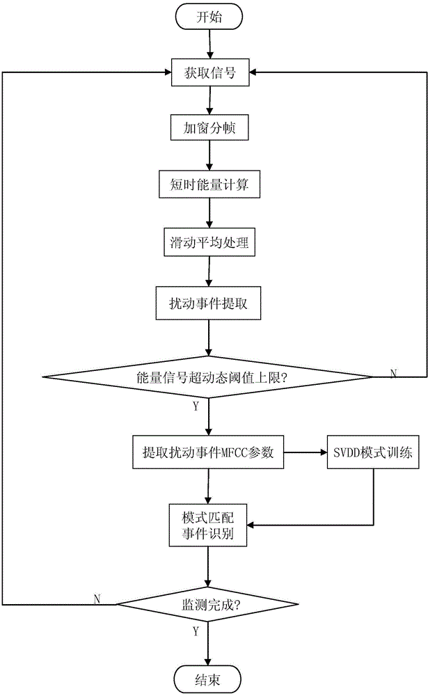
[0093] The pattern recognition method embodiment of this optical fiber sensing vibration signal is experimented on a long 3km optical fiber sensing system, and the flow process of this example method is as follows figure 1 As shown, it specifically includes the following steps:

[0094] Step 1: Signal Acquisition

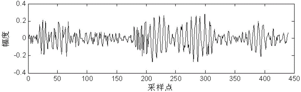
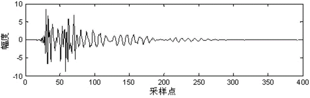
[0095] The optical fiber sensing system converts the collected optical signal into an electrical signal, and obtains a discrete digital signal s(n) through AD sampling, where n is the number of sampling points; figure 2 with 3 Shown are the discrete signal waveforms collected by the optical fiber sensing system when it rains and the discrete signal waveforms when people climb, respectively.

[0096] Step 2: Framing and windowing

[0097] In this example, the Hamming window is selected for windowing processing, and the single frame length is se...


PUM


Abstract

The invention relates to a method for identifying an optical fibre sensing vibration signal. The method comprises the following specific steps: (1), obtaining the signal so as to obtain a discrete digital signal s(n); (2), windowing and framing to obtain a kth-frame windowed signal sk(n); (3), calculating to obtain a kth-frame energy signal e(k); (4), obtaining an energy signal e'(k) after moving average processing; (5), extracting a disturbance event, comparing the e'(k) with dynamic threshold values Th1 and Th2, intercepting a continuous signal as a disturbance event signal, and determining that no any disturbance event happens if the e'(k) is not beyond the Th1; (6), solving an MFCC (Mel Frequency Cepstrum Coefficient) parameter of the disturbance event, obtaining a feature set of Y type events; and establishing a pattern base of Y type disturbance events; (7), performing SVDD (Support Vector Data Description) training; and (8), matching a feature parameter set of an event to be detected with an SVDD training model in the pattern base, judging which the event to be detected belongs to, or judging that the event to be detected is an unknown event. By means of the method disclosed by the invention, the identification accuracy of the optical fibre sensing signal is improved; false reports are reduced; pattern training of single disturbance event can be completed; and the database establishing complexity is reduced.

Description

technical field [0001] The invention belongs to pattern recognition technology, and in particular relates to a method for recognizing vibration signals of optical fiber sensing in an optical fiber sensing system. Background technique [0002] The optical fiber sensing system adopts the optical cable as a two-in-one sensor and transmission device. By directly touching the optical cable or passing through the load, such as covering soil, barbed wire, fences, etc., the various vibration signals transmitted to the optical cable are continuously analyzed. Real-time monitoring, collecting disturbance data, and after back-end analysis and processing and intelligent identification, it can determine different types of external interference, such as climbing barbed wire, fences, walking in fortified areas, digging holes and opening walls, and damages that may threaten the loads of optical cables, etc. , eliminate external interference signals, realize system early warning or real-time...

Claims


Application Information

Patent Timeline
Patent Type & Authority Applications(China)
IPC IPC(8): G06F19/00G08B13/186
Inventor 唐超胡挺刘志强张旭伟杨军杨庆瑞时帅
Owner NO 34 RES INST OF CHINA ELECTRONICS TECH GRP
Why Eureka
Try Eureka