Supercharge Your Innovation With Domain-Expert AI Agents!

light detector

A light detector and photoreceptor technology, applied in the field of light sensors, can solve problems such as poor anti-interference ability of light detectors, and achieve the effects of enhancing anti-interference ability, improving sensitivity, and solving poor anti-interference ability.

Active Publication Date: 2018-07-20
SEMICON MFG INT (SHANGHAI) CORP
View PDF8 Cites 0 Cited by
  • Summary
  • Abstract
  • Description
  • Claims
  • Application Information

AI Technical Summary

Problems solved by technology

[0005] The main purpose of the present invention is to provide a photodetector to solve the problem of poor anti-interference ability of the photodetector

Method used


Image

  • light detector
  • light detector
  • light detector

Examples


Embodiment Construction

[0024] It should be noted that the embodiments in the application and the features in the embodiments can be combined with each other if there is no conflict. Hereinafter, the present invention will be described in detail with reference to the drawings and in conjunction with the embodiments.

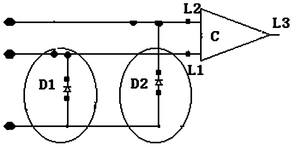
[0025] According to an embodiment of the present invention, a photodetector is provided, figure 2 It is a schematic circuit diagram of a photodetector according to an embodiment of the present invention.

[0026] Such as figure 2 As shown, the photodetector includes: a first photoreceptor D1, a second photoreceptor D2 and a comparator C.

[0027] The first photoreceptor D1 is used to detect the light signal to obtain the detection signal. A cover layer for isolating optical signals is provided on the outside of the second photoreceptor D2 for providing reference signals. The detection signal obtained by the first photoreceptor D1 and the reference signal provided by the second photorecepto...


PUM


Abstract

The present invention discloses an optical detector. The optical detector comprises: a first photosensitive device that is used for detecting an optical signal to obtain a detection signal; a second photosensitive device, wherein a cover layer used for isolating the optical signal is disposed at an exterior side of the second photosensitive device, and the second photosensitive device is used for providing a reference signal; and a comparator that is used for obtaining a logic control signal according to the detection signal and the reference signal, wherein the comparator comprises: a first input end, a second input end and an output end; the first input end is connected with the first photosensitive device and is used for inputting the detection signal; the second input end is connected with the second photosensitive device and is used for inputting the reference signal; and the output end is used for outputting the logic control signal. According to the optical detector provided by the present invention, an interference resistance effect can be enhanced.

Description

Technical field [0001] The present invention relates to the field of light sensors, in particular to a light detector. Background technique [0002] Traditional light detectors or light sensor circuits usually use pixel units to detect high-intensity light, and then output a logic signal, which is related to the intensity of light. In the security application of smart cards such as bank cards, in order to prevent illegal personnel from obtaining the data information in the bank card by removing the card, light detectors or light sensors are usually used to detect the light signal. When the light signal is detected, the level signal is output. The internal circuit of the bank card is short-circuited and other methods are used to destroy the internal data information of the bank card, so that some criminals cannot obtain the data information in the bank card after the card is opened. However, the chip size in the pixel unit circuit of the traditional light detector or light sensor...

Claims


Application Information

Patent Timeline
Patent Type & Authority Patents(China)
IPC IPC(8): G06F21/86
Inventor 王昕宇周世聪倪昊
Owner SEMICON MFG INT (SHANGHAI) CORP
Features
  • R&D
  • Intellectual Property
  • Life Sciences
  • Materials
  • Tech Scout
  • Unparalleled Data Quality
  • Higher Quality Content
  • 60% Fewer Hallucinations
Learn More