Radio frequency optical transceiver case having electromagnetic shielding function

A technology of electromagnetic shielding and radio frequency light, applied in the direction of magnetic field/electric field shielding, electrical components, etc., can solve problems such as equipment mutual interference, electromagnetic radiation control, increase shielding, etc., and achieve the effect of solving electromagnetic compatibility problems

Inactive Publication Date: 2015-11-25
ANHUI CANBANG ELECTRIC
View PDF6 Cites 2 Cited by
  • Summary
  • Abstract
  • Description
  • Claims
  • Application Information

AI Technical Summary

Problems solved by technology

However, with the rapid development of electronic information technology, the electromagnetic environment in which RF optical transceivers are located is becoming more and more complex. Even in the same system, due to the increase in the number of devices, mutual interference between devices is caused, and the electromagnetic compatibility performance of RF optical transceivers is getting worse. more and more attention
[0003] With the increase of the operating frequency and circuit complexity of the RF optical transceiver circuit, it is difficult to control the electromagnetic radiation in an acceptable range only by reasonable circuit design. In addition, it is necessary to increase the shielding from the structure of the optical transceiver chassis.

Method used


Image

  • Radio frequency optical transceiver case having electromagnetic shielding function

Examples


Embodiment Construction

[0013] The present invention will be described in detail below with reference to the accompanying drawings and in combination with embodiments.

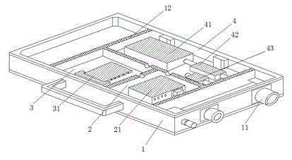
[0014] Such as figure 1 As shown, a radio frequency optical transceiver chassis with electromagnetic shielding function includes a box body 1 made of all-aluminum milling. The box body 1 is provided with at least one interface 11 outside, and the box body 1 is provided with a Formed at least one baffle 12, the inner cavity of the box body 1 is divided into a first cavity 2, a second cavity 3 and a third cavity 4 through the baffle 12, and the first cavity 2 is provided with a power module 21. The second cavity 3 is provided with an optical isolation module 31 that is susceptible to interference, and the third cavity 4 is provided with a pre-distortion correction and electro-optical conversion module 41 that is not easy to generate interference signals, a low-noise amplification unit 42 and an impedance In the matching module 43, the...


PUM


Abstract

The invention discloses a radio frequency optical transceiver case having an electromagnetic shielding function. The radio frequency optical transceiver case comprises a box body, wherein the box body is made by all-aluminum milling, at least one interface is arranged outside the box body, at least one baffle plate is arranged in the box body and integratedly formed with the box body, an inner cavity of the box body is divided into a first cavity body, a second cavity body and a third cavity by the baffle plate, the first cavity body is provided with a power supply module, an optical isolation module susceptible to interference is arranged in the second cavity body, a pre-distortion correction and electro-optical conversion module which is difficult to generate an interference signal, a low-noise amplification unit and an impedance matching module are arranged in the third cavity body, and the first cavity body, the second cavity body and the third cavity body are electrically connected through a feed-through filter. With the adoption of a cavity division mode, components susceptible to interference are arranged in respectively closed spaces, components insusceptible to interference are arranged in the same divided cavity, and thus, the problem of electromagnetic compatibility of the radio frequency optical transceiver is solved better.

Description

technical field [0001] The invention relates to an optical transceiver chassis, in particular to a radio frequency optical transceiver chassis with electromagnetic shielding function. Background technique [0002] The main function of the RF optical transceiver is to convert the RF signal into an optical signal and carry out long-distance transmission. Compared with the traditional cable transmission optical transmission system, it has special advantages such as long distance, strong confidentiality, no electromagnetic radiation and anti-electronic interference. Therefore, RF The application of optical transmission systems in various fields is becoming more and more popular. However, with the rapid development of electronic information technology, the electromagnetic environment in which RF optical transceivers are located is becoming more and more complex. Even in the same system, due to the increase in the number of devices, mutual interference between devices is caused, a...

Claims


Application Information

Patent Timeline
Patent Type & Authority Applications(China)
IPC IPC(8): H05K9/00
Inventor 刘业军
Owner ANHUI CANBANG ELECTRIC
Why Eureka
Try Eureka