Eureka AIR delivers breakthrough ideas for toughest innovation challenges, trusted by R&D personnel around the world.

Self-cleaning-floatation-filtration treatment facility

A treatment equipment and self-cleaning technology, applied in the field of water treatment, can solve the problems of complex automatic control configuration, complex automatic control system, low reliability, etc., and achieve the effects of simple automatic control configuration, overcoming complex structure and low maintenance cost.

Active Publication Date: 2015-12-02
CENT RES INST OF BUILDING & CONSTR CO LTD MCC GRP +1
View PDF4 Cites 3 Cited by
  • Summary
  • Abstract
  • Description
  • Claims
  • Application Information

AI Technical Summary

Problems solved by technology

Because the air flotation filter process combines the two processes of air flotation and filtration, although the space is saved, compared with the separate and independent operations, the number of related supporting electrical equipment has not been reduced. The automatic control system It also becomes more complicated, and the equipment investment and operation and maintenance costs are also higher
In addition, in response to the impact of water quality impact loads such as the concentration of suspended solids and turbidity in the influent, we can only rely on adjusting the length of the filtration cycle to deal with the impact of impact loads on the quality of the produced water.
[0009] In the process of realizing the present invention, the inventor found that there are at least defects in the prior art such as complex structure, large footprint, low reliability, complex automatic control configuration, and high operation and maintenance costs

Method used


Image

  • Self-cleaning-floatation-filtration treatment facility
  • Self-cleaning-floatation-filtration treatment facility
  • Self-cleaning-floatation-filtration treatment facility

Examples


Embodiment Construction

[0042] The preferred embodiments of the present invention will be described below in conjunction with the accompanying drawings. It should be understood that the preferred embodiments described here are only used to illustrate and explain the present invention, and are not intended to limit the present invention.

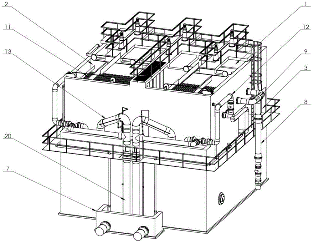
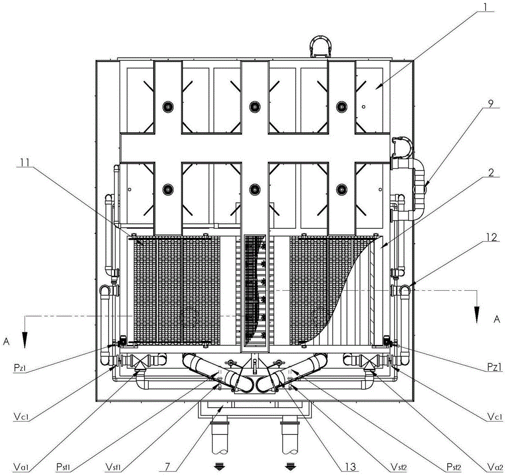
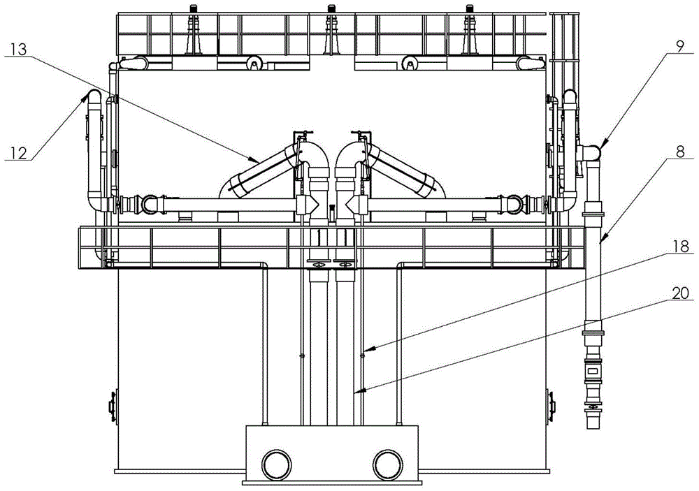
[0043] According to an embodiment of the present invention, such as Figure 1-Figure 8 As shown, a self-cleaning floating filter water treatment equipment is provided.

[0044] Coagulation, air flotation equipment and gravity valveless filter tank filtration equipment are now coupled into a self-cleaning flotation filtration water treatment equipment. The equipment's coagulation reaction, air flotation, filtration, product water storage, waste water discharge and other functional areas are not only independent, but also naturally connected to form an organic whole through a reasonable water distribution system. The auxiliary equipment of this equipment is integrate...


PUM

PropertyMeasurementUnit
thicknessaaaaaaaaaa
particle sizeaaaaaaaaaa

Abstract

The invention discloses a self-cleaning-floatation-filtration treatment facility which is divided into three layers from top to bottom in the vertical direction, wherein the first layer is provided with a coagulation reaction region and a floatation region; the second layer is provided with a facility layout region and a self-cleaning water storage region; and the third layer is provided with a stable regulation region, a filtration region and a drainage region. The self-cleaning-floatation-filtration treatment facility completely implements the self-cleaning process by reasonably regulating the water inflow and water production on the basis of the hardware configuration, can complete the technical process of coagulation, floatation, filtration, stable disinfection and the like in one facility, and can overcome the defects of complex structure, large occupied area, complex automatic control configuration, low reliability, high operating maintenance cost and the like, thereby implementing the advantages of integrated structure, small occupied area, simple automatic control configuration, high reliability and low operating maintenance cost.

Description

technical field [0001] The invention relates to the technical field of water treatment, in particular to a self-cleaning floating filter water treatment equipment. Background technique [0002] In the field of water treatment engineering, coagulation, air flotation and filtration are widely used water treatment processes, and are usually used in series. Coagulation, air flotation and filtration processes are widely used in surface water treatment projects, sewage recycling projects, landscape water cycle purification projects, or reverse osmosis membrane seawater desalination projects. However, the traditional coagulation and air flotation process also has problems such as being affected by the impact load of water quality such as suspended solids and turbidity in the influent, and the effluent water quality fluctuates greatly, and the effluent is uneven, easy to short flow, and easy to settle. In addition, although the integrated new technology of multiple air flotation fi...

Claims


Application Information

Patent Timeline
Patent Type & Authority Applications(China)
IPC IPC(8): C02F9/04
Inventor 鞠然兰菲吴月华
Owner CENT RES INST OF BUILDING & CONSTR CO LTD MCC GRP
Why Eureka
Eureka Blog
Learn More