Bearing with power generation function

A bearing and functional technology, applied in the field of bearings with power generation function, can solve the problems of complex structure, large space ratio, high cost, etc., and achieve the effect of small size, simple structure and simple bearing structure

Inactive Publication Date: 2015-12-02
ESTUN AUTOMATION TECH
View PDF9 Cites 5 Cited by
  • Summary
  • Abstract
  • Description
  • Claims
  • Application Information

AI Technical Summary

Problems solved by technology

This kind of mechanism not only has a complex structure, but also takes up a large space, and it is expensive, and it is troublesome to maintain and replace.

Method used


Image

  • Bearing with power generation function
  • Bearing with power generation function
  • Bearing with power generation function

Examples


Embodiment Construction

[0017] The present invention will be described in further detail below in conjunction with the accompanying drawings and embodiments.

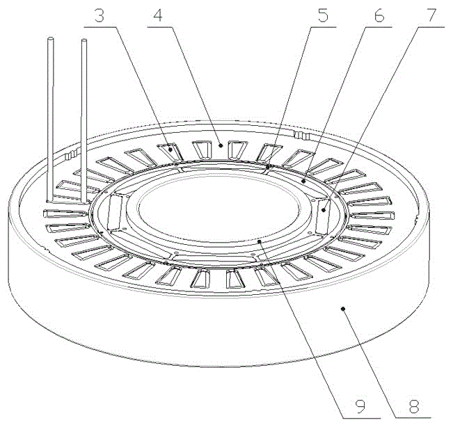
[0018] Such as Figure 5 As shown, the rotor punches made of 1J22 (Co50V2) material are laminated to a suitable size and height by a lamination process to form a ring-shaped rotor 6 . The annular rotor is uniformly provided with eight magnetic steel mounting holes along the circumferential direction of the annular rotor. Insert the magnetized steel 7 made of samarium-cobalt permanent magnet material with a height equal to the thickness of the annular rotor 6 into the corresponding magnetic steel installation hole on the annular rotor 6 and fasten it. The number of 7 magnetic steels is eight , when the magnetic steel is inserted into the magnetic steel installation hole of the annular rotor 6, it is installed on the opposite pole in the diameter direction. The so-called opposite pole installation means that the adjacent magnetic poles of two ...


PUM


Abstract

The invention discloses a bearing with a power generation function. A ring-shaped rotor is fastened to an inner bearing ring. All roller pins are evenly installed on a roller pin retaining ring. The roller pin retaining ring is fastened to the outer ring face of the ring-shaped rotor. A roller pin guide rail ring is fastened to the inner ring face of a ring-shaped stator. An outer bearing ring is fastened to the outer ring face of the ring-shaped stator. All the roller pins are limited to roll in the roller pin guide rail ring. The ring-shaped rotor is evenly provided with multiple pieces of magnetic steel in the circumferential direction of the circular ring of the ring-shaped rotor. The ring-shaped stator is evenly provided with a plurality of copper wire windings in the circumferential direction of the circular ring of the ring-shaped stator. All the copper wire windings are connected in series continuously and a pair of leads is led out from the copper wire windings. The magnetic steel forms a magnetic field. When the inner bearing ring rotates, a magnetic force line is cut by the copper wire windings, and an electric current is generated. According to the bearing with the power generation function, a power generation mechanism and the bearing structure are reasonably assembled into a whole, so that the bearing is simple in structure and small in size; on the premise that the power generation function of the bearing is achieved, the relatively simple bearing structure is maintained.

Description

technical field [0001] The invention relates to a bearing, in particular to a bearing with power generation function. It is used in occasions where it is necessary to supply power while using bearings to rotate, or to convert and store kinetic energy into electrical energy. Background technique [0002] Bearings are precision mechanical devices. There are applications in various industries and fields. However, for example, in industries such as wind power generation, motor servo, automobiles, and electric vehicles, there are demands for electrical energy conversion and storage along with rotation. For this requirement, in addition to the bearing, it is generally used in combination with a transmission mechanism and a power generation mechanism to achieve the purpose. This kind of mechanism is not only complex in structure and takes up a large space, but also has a high cost and is troublesome to maintain and replace. Contents of the invention [0003] The technical pro...

Claims


Application Information

Patent Timeline
IPC IPC(8): F16C19/46F16C41/00
Inventor 刘冬戴安刚李金吴波
Owner ESTUN AUTOMATION TECH
Why Eureka
Try Eureka