
Time domain raised cosine three-level offset carrier modulation method

A time-domain raised cosine and offset carrier technology, which is applied in the field of satellite navigation system signal realization, can solve the problems of reduced power amplifier efficiency, code tracking performance, and unsatisfactory anti-multipath and anti-interference capabilities.

Active Publication Date: 2015-12-02
HARBIN ENG UNIV
View PDF5 Cites 0 Cited by
  • Summary
  • Abstract
  • Description
  • Claims
  • Application Information

AI Technical Summary

Problems solved by technology

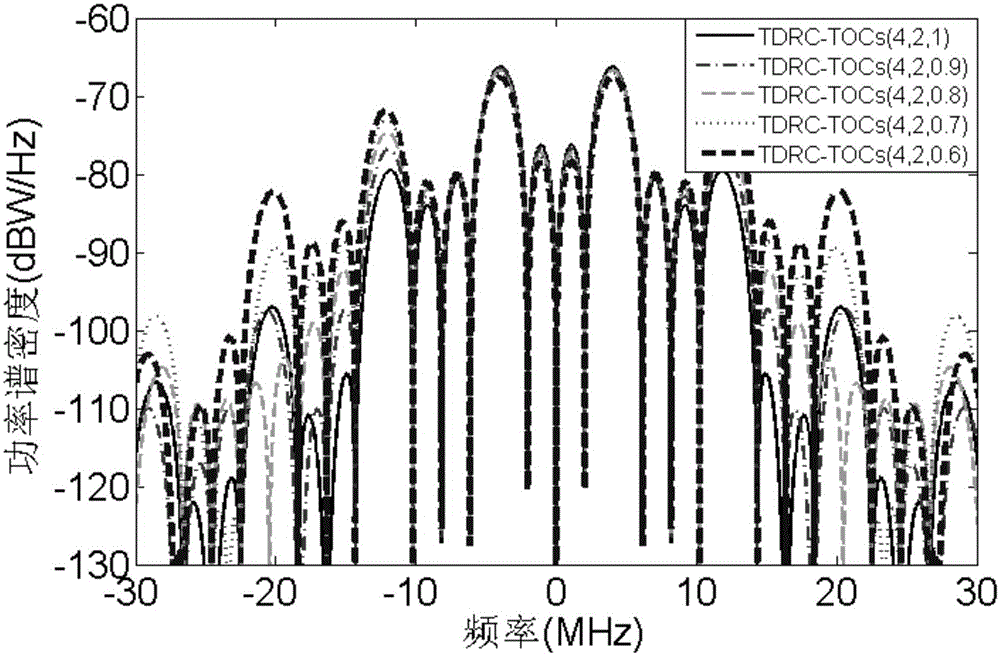
The BOC modulation method given in the article will lead to a large-amplitude sidelobe outside the band and reduce the efficiency of the power amplifier, and the code tracking performance, anti-multipath and anti-interference ability of the signal are still not ideal. For the above shortcomings, the present invention proposes a time-based Domain raised cosine pulse three-level symbol offset carrier modulation method (TimeDomainRaisedCosineThree-levelsOffsetCarrier, TDRC-TOC(n,m,ρ)), in which the subcarrier signal can take values ​​of ±1 and 0, and the ±1 signal waveform is determined by the time domain The raised cosine pulse indicates that this method not only provides more choices for the design of navigation signals, but also can effectively reduce the large side lobe of the power spectrum, reduce the interference to adjacent signals, and improve the power efficiency of navigation signals. It has better code tracking performance, anti-multipath and anti-jamming capabilities, which is of great significance for improving the navigation and positioning capabilities of the navigation system

Method used


Image

  • Time domain raised cosine three-level offset carrier modulation method
  • Time domain raised cosine three-level offset carrier modulation method
  • Time domain raised cosine three-level offset carrier modulation method

Examples


Embodiment Construction

[0047] Below in conjunction with accompanying drawing and embodiment the present invention will be further described:

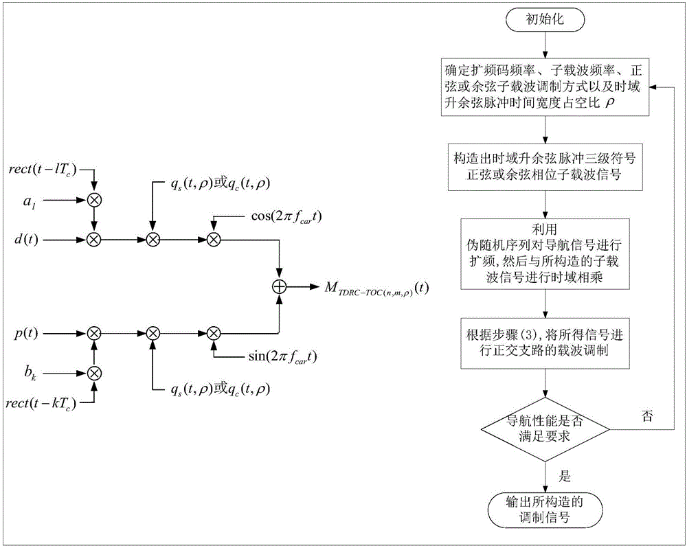
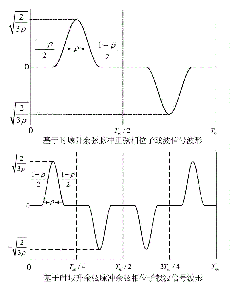
[0048] figure 1 and figure 2 Respectively the TDRC-TOC signal modulation model proposed by the present invention, the flow chart of the implementation method and the subcarrier signal waveform, wherein figure 1 The definitions of the symbols in are as follows:

[0049] d(t): navigation signal data channel information;

[0050] p(t): pilot channel information;

[0051] a l : Pseudo-random spreading code sequence of the in-phase branch;

[0052] b l : Pseudo-random spreading code sequence of the orthogonal branch;

[0053] rec(t): rectangular gate function;

[0054] q s (t, ρ): the described one based on time-domain raised cosine pulse three-level symbol sine phase subcarrier signal waveform;

[0055] q c (t, ρ): the described one based on time-domain raised cosine pulse three-level symbol cosine phase subcarrier signal waveform;

[0056] m TDRC-T...


PUM


Abstract

The invention aims to provide a time domain raised cosine three-level offset carrier (TDRC-TOC (m, n, Rho)) modulation method, comprising the processes of: first, determining a spreading code frequency fc, a subcarrier frequency fsc, a sine or cosine phase subcarrier modulation mode and a time domain raised cosine pulse time width duty ratio Rho, and constructing time domain raised cosine three-level sine or cosine phase subcarrier signals; and second, utilizing a pseudorandom sequence to perform spread spectrum on navigation signals, then performing subcarrier modulation, and finally performing orthogonal branch carrier modulation on obtained signals. The method can generate signals of constant amplitudes to flexibly adjust the main lobe and side lobe split degree of a signal power spectrum, thereby allowing the navigation signals to possess the characteristics of good code tracking performance, high anti-interference and anti-multipath capability, and great compatible capability with signals of other systems; meanwhile the method can avoid side blobs of large amplitudes, and improve frequency spectrum efficiency, and is especially suitable for the satellite navigation service employing a high efficiency nonlinear amplifier and having the power and bandwidth limited.

Description

Technical field: [0001] The invention relates to a method for realizing satellite navigation system signals, in particular to a three-level symbol offset carrier modulation method based on time domain raised cosine pulse. Background technique: [0002] The navigation signal system is in the most critical position in the top-level design of the satellite navigation system. Its performance directly determines the navigation and positioning performance of the system. Navigation signal modulation is the most important thing in the design of the navigation signal system. In order to enable multiple signals to better share the limited frequency band of the Global Navigation Satellite System (GNSS), and to further improve the ranging accuracy and anti-interference performance of the signal, new signal modulation methods are constantly emerging. Binary Offset Carrier (Binary Offset Carrier, BOC(n, m)) is a new modulation method that can meet the above requirements, in which the freq...

Claims


Application Information

Patent Timeline
IPC IPC(8): G01S19/37
CPCG01S19/37
Inventor 赵旦峰孙岩博薛睿曹庆铭吕雪孙兵兵
Owner HARBIN ENG UNIV
Learn More