

Ion thruster beam test method based on Faraday probe array
A technology of ion thrusters and probe arrays, which is applied in the direction of radiation measurement, instruments, and measuring devices, to achieve the effects of improving reliability, large amount of data information, and simplifying the structure
- Summary
- Abstract
- Description
- Claims
- Application Information
AI Technical Summary
Problems solved by technology
Method used
Image

Examples
Embodiment Construction
[0048] The present invention will be described in detail below with reference to the accompanying drawings and examples.
[0049] Step 1. Build a test device.
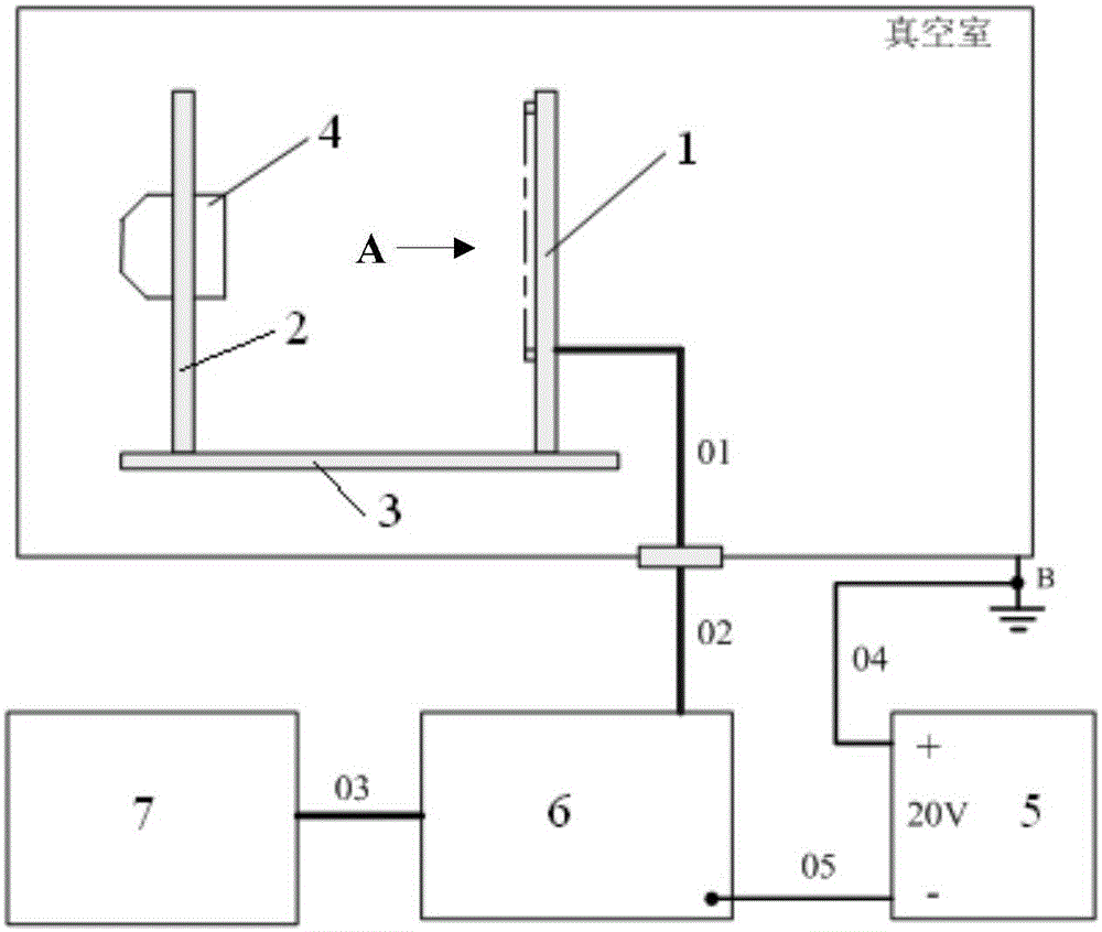
[0050] Such as figure 1 As shown, the Faraday probe array 1 and the ion thruster 4 are placed in the vacuum chamber, and the supporting bias power supply 5, test circuit board 6, and test computer 7 are placed outside the vacuum chamber, and they together form a test system. 01, 02, 03, 04, and 05 are test cables.
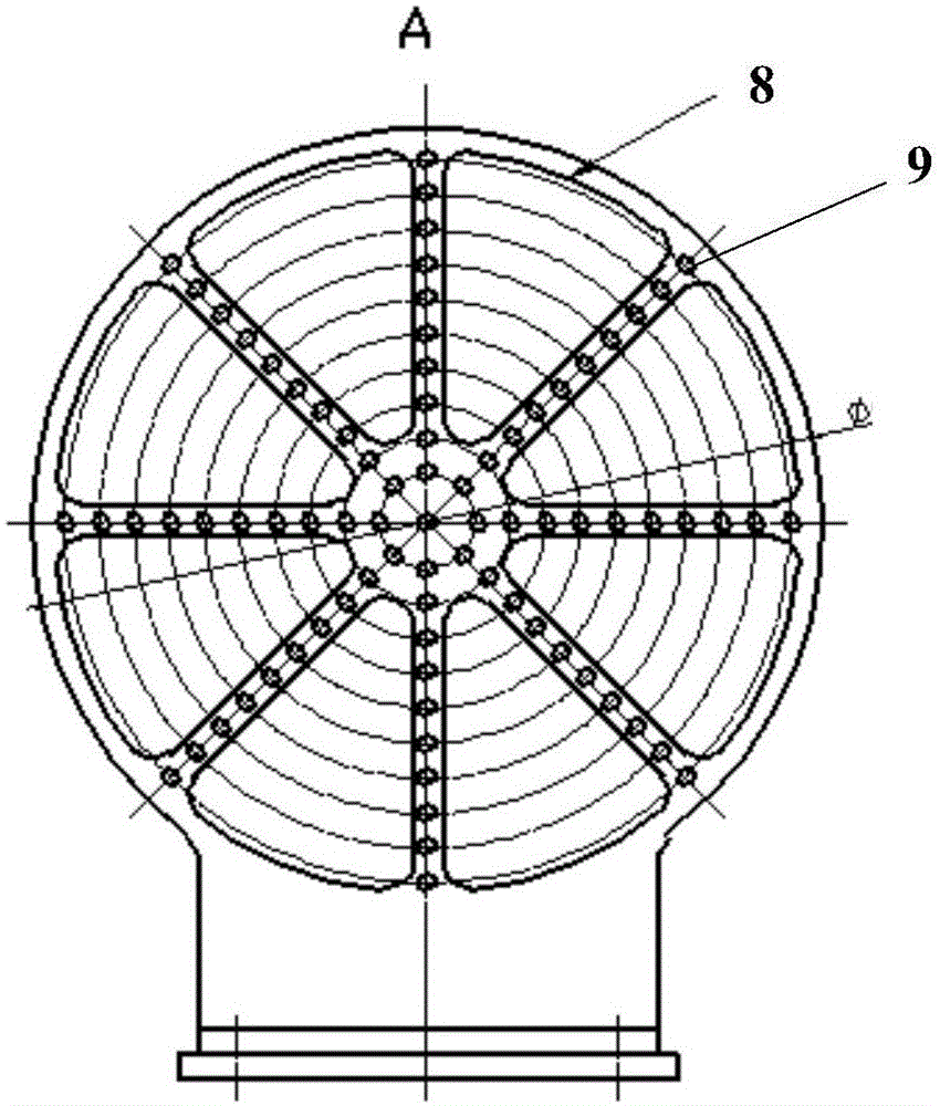
[0051]The Faraday probe array 1 is formed by arranging a plurality of Faraday probes. The arrangement method is: the Faraday probes are arranged radially and form a series of concentric circles; the Faraday probes on the same radial line form a group; there are M groups and N circles of Faraday probes.
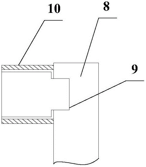
[0052] like figure 2 As shown, the Faraday probe array 1 is made up of a Faraday probe 9 and a disc-shaped metal support 8 made of conductive metal. The disc-shaped metal support 8 consists of a centra...
PUM
 Abstract
Description
Claims
Application Information