Demagnetizing circuit and method for removing residual magnetism of electromagnetic current transformer on line

A current transformer, electromagnetic technology, applied in inductors, circuits, transformers, etc., can solve the problems of reduced magnetic circuit efficiency, reduced measurement accuracy, increased magnetic flux leakage, etc., to achieve fast demagnetization speed, improve accuracy, and improve The effect of precision

Active Publication Date: 2015-12-02
ZHEJIANG UNIV
View PDF7 Cites 9 Cited by
  • Summary
  • Abstract
  • Description
  • Claims
  • Application Information

AI Technical Summary

Problems solved by technology

At present, people have carried out research on this issue, for example, if the iron core of the protective transformer has an air gap, the residual magnetism can be limited to less than 10%, and the transient characteristics are greatly improved, but the magnetic resistance is large and the magnetic circuit efficiency is high. Reduction will also increase magnetic flux leakage and reduce measurement accuracy, and it is inconvenient to manufacture; for metering current transformers, closed-circuit or open-circuit demagnet

Method used


Image

  • Demagnetizing circuit and method for removing residual magnetism of electromagnetic current transformer on line
  • Demagnetizing circuit and method for removing residual magnetism of electromagnetic current transformer on line
  • Demagnetizing circuit and method for removing residual magnetism of electromagnetic current transformer on line

Examples


Embodiment Construction

[0021] Below in conjunction with accompanying drawing of description, the present invention will be further described.

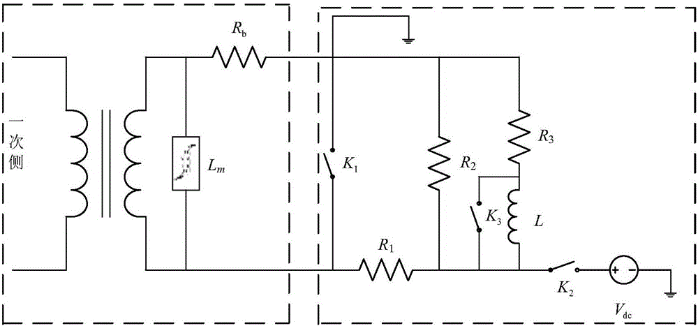
[0022] as attached figure 1 As shown, in the demagnetization circuit used to eliminate the residual magnetism of the electromagnetic current transformer online, the excitation inductance L of the current transformer m Parallel to the secondary side, grounded winding equivalent resistance R b Located at one end of the secondary side; characterized in that the demagnetization circuit includes a third resistor R 3 A series structure composed of inductance L, in which both ends of inductance L are also connected in parallel with the third switch K 3 ; The series structure and the second resistor R 2 and the first switch K 1 are connected in parallel to both ends of the secondary side of the current transformer; the third resistor R 3 The outer end of the inductor L is grounded, and the outer end of the inductor L passes through the second switch K 2 connec...


PUM


Abstract

The present invention relates to the electric power automation technology, and aims to provide a demagnetizing circuit and method for removing residual magnetism of an electromagnetic current transformer on line. The demagnetizing circuit comprises a series connection structure formed by a third resistor and an inductor, a third switch is also connected in parallel at two ends of the inductor, the series connection structure is connected in parallel at two ends of a secondary side of a current transformer with a second resistor and a first switch, an outer end of the third resistor is earthed, an outer end of the inductor is connected to one end of a direct current power supply through a second switch, the other end of the direct current power supply is earthed, and a first resistor is disposed between the second resistor and a non-earthing end of the first switch. With adoption of the circuit and the method, the residual magnetism inside the current transformer is removed within a very short time when the switches are disconnected, and the accuracy of relay protection setting calculation and the reliability of relay protection actions are raised. The residual magnetism can be removed on line, and the current transformer does not need to be out of service. No complicated signal detection circuits or control circuits are required, and the circuit is easy to realize. The error of residual magnetism of an iron core after demagnetizing is small, and the demagnetizing speed is high.

Description

technical field [0001] The invention relates to a circuit and a method for on-line eliminating the residual magnetism of an electromagnetic current transformer, which belongs to the electric power automation technology. Background technique [0002] Electromagnetic current transformer is a standard measurement and protection test equipment widely used in power system. In the case of line cut-off operation or short-circuit fault in the power system, there will be a considerable DC component in the line current during the transient process, which will cause residual magnetism in the iron core, resulting in a decrease in the magnetic permeability of the iron core and thus affecting the transformer. performance. [0003] For protective current transformers, the existence of a large amount of residual magnetism will aggravate the saturation degree of the iron core and shorten the saturation time, which is an important reason for unbalanced current and differential protection mis...

Claims


Application Information

Patent Timeline
IPC IPC(8): H01F13/00H01F38/28
Inventor 郑太英胡恩德杨欢赵荣祥
Owner ZHEJIANG UNIV
Why Eureka
Try Eureka