Battery with electrolyte mixing device

A technology of electrolyte and liquid electrolyte, applied in the direction of transferring electrolyte devices, batteries, secondary batteries, etc., can solve the problems of limiting vehicle acceleration, achieve high service life, improve service life, and good performance

Active Publication Date: 2015-12-02
IQ POWER LICENSING +1
View PDF8 Cites 4 Cited by
  • Summary
  • Abstract
  • Description
  • Claims
  • Application Information

AI Technical Summary

Problems solved by technology

The magnitude of the vehicle acceleration is limited because the energy used to run the acid in the channel is generated by the vehicle acceleration

Method used


Image

  • Battery with electrolyte mixing device
  • Battery with electrolyte mixing device
  • Battery with electrolyte mixing device

Examples


Embodiment Construction

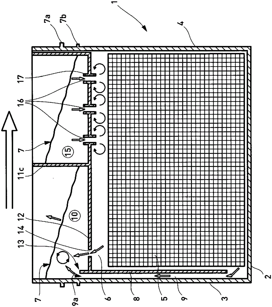
[0034] figure 1 A cross-sectional view of a battery box cell is shown. The battery box cell 1 has a rectangular cross-section with a bottom 2 and four side walls, only side walls 3 and 4 being visible in this view. The plate-shaped electrode is identified with reference numeral 5 and the battery acid with a fill level 7 between a maximum fill level 7a and a minimum fill level 7b is marked with a reference sign 6 . As can be seen from the figure, the level plotted is at the mark of the maximum level 7a.

[0035] A flow channel plate 8 is arranged vertically between the side wall 3 and the electrode 5 , thereby forming a flow channel 9 . The end of the flow channel 9 is thus an outflow groove 9 a.

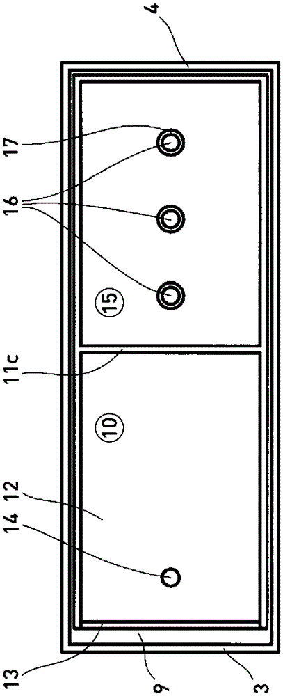
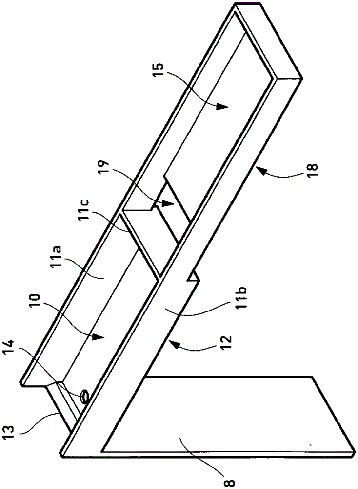
[0036] On the edge of the outflow trough 9a, a mixing basin 10 is arranged, which has side walls 11a, 11b, 11c and a bottom 12, wherein the side walls 11a and 11b can only be viewed in a perspective view. Figure 8 seen in. The upper end of the flow channel plate 8 forms an over...


PUM


Abstract

The invention relates to a battery comprising liquid electrolyte, used in moving vehicles, wherein the battery includes a battery housing comprising side walls, a housing floor and a cover, a liquid electrolyte, the level of which is within predetermined tolerance limits, electrodes, a flow channel plate arranged at least on one side wall so as to form .a flow channel, wherein the upper end of said flow channel serves as exhaust port, a mixing vessel comprising a mixing vessel floor and mixing vessel side walls being arranged above the electrodes wherein the mixing vessel side wall adjoining the exhaust port is formed as an overflow the mixing vessel floor being located below the minimum level for the liquid electrolyte, which minimum level is provided for operational reasons, and at least one floor opening being provided in the mixing vessel floor.

Description

technical field [0001] The invention relates to a battery with a liquid electrolyte, which is preferably used in a moving vehicle, for example in a car, a boat or an airplane, and which has a device for mixing the electrolyte. Background technique [0002] The automotive industry's commitment to lightweight construction also involves cutting battery weight. At the same time, however, the requirements for higher battery efficiency are increasing because, in addition to the conventional energy for starting e.g. Energy for electric heated seats. Furthermore, it is desirable that the battery efficiency be kept at a constant high level as much as possible over the service life of the battery, since more and more electricity is also used to control and operate safety-relevant functional units such as steering and brakes . Battery efficiency is understood below to mean the capacity of the battery and the capacity of the battery to deliver current or to receive current. Cell eff...

Claims


Application Information

Patent Timeline
Patent Type & Authority Applications(China)
IPC IPC(8): H01M2/38
CPCH01M2/38H01M10/12H01M10/4214H01M2220/20Y02E60/10H01M50/70Y02P70/50
Inventor 查尔斯·罗伯特·沙利文S.奇尔希
Owner IQ POWER LICENSING
Why Eureka
Try Eureka