Shank structure for cutter clamping

A tool handle structure and cutting tool technology, which is applied to the accessories of tool holders, manufacturing tools, turning equipment, etc., can solve the problems of high precision of taper surface, high use cost, uneven force, etc., and achieve good connection stability, Low cost of use and good positioning effect

Active Publication Date: 2015-12-09
NINGBO CHUANJINGYU MECHANICAL TECH DEV
View PDF7 Cites 8 Cited by
  • Summary
  • Abstract
  • Description
  • Claims
  • Application Information

AI Technical Summary

Problems solved by technology

But the problem is that the collet and the handle of the prior art are generally only positioned by the slope of the front end of the collet and the outer cone section of the collet, and the outer cone section usually adopts a larger taper. Both the clamping force and the stability of the clamping are insufficient
And after long-term use, it is inevitable that there will be a certain deviation in the thread fit before the connection between the nut and the handle, and the force between the collet and the handle will be uneven. The outer cone section of the collet and the inner cone of the handle The fitting surfaces between segments are prone to slight scratches or abrasions, which will not only greatly affect the clamping force and centering accuracy between the tool handle and the collet, but also cause some fitting surfaces to be tightly assembled, making it difficult for the collet to When pulling out from the holder shaft hole
But the problem is that the collet of the prior art has too high requirements on the precision of the taper surface, and it is difficult to process it by simple sandpaper grinding. Therefore, the structure of the tool handle of the prior art has a short service life, needs to be replaced frequently, and has a high cost of use.

Method used


Image

  • Shank structure for cutter clamping
  • Shank structure for cutter clamping
  • Shank structure for cutter clamping

Examples


Embodiment Construction

[0017] Embodiments of the present invention will be further described below in conjunction with the accompanying drawings.

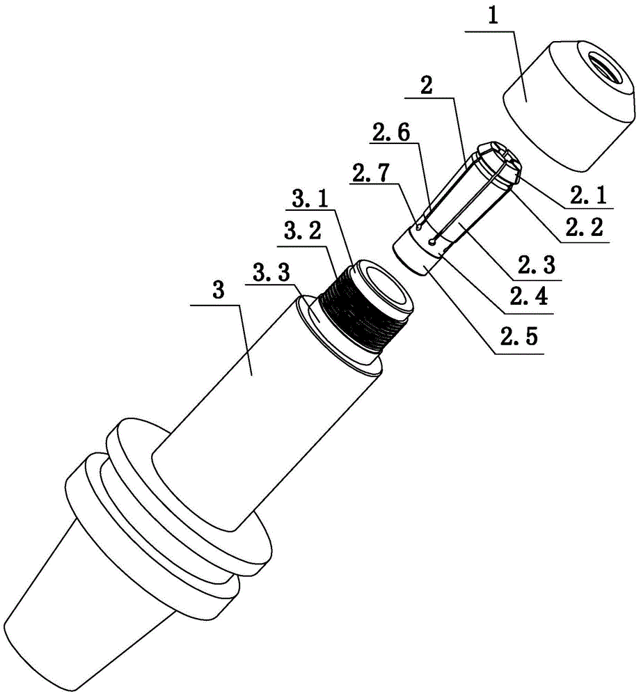
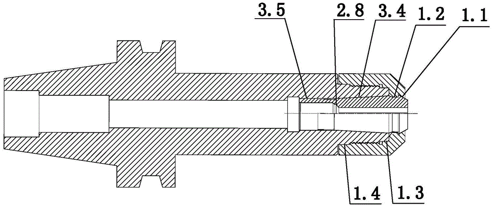
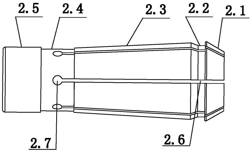
[0018] Such as Figure 1-3 As shown, a handle structure for tool clamping includes a handle body 3, a collet 2 and a nut 1, and the front end of the collet 2 is provided with an inclined surface for matching with the inner inclined wall 1.1 of the nut 1 2.1 and the annular snap groove 2.2 for engaging with the snap ring 1.2 provided in the inner cavity of the nut 1, and the middle section of the collet 2 is an outer cone section 2.3, and the front part of the tool handle body 3 is provided for engaging with the nut. 1, the matching connecting part, the tool handle body 3 is provided with a hollow shaft hole, and the inner cavity of the shaft hole is provided with an inner cone section 3.4 for matching with the outer cone section 2.3 of the collet 2, and the collet 2 is provided with multiple The sectional groove 2.6 that can shrink along the direction o...


PUM


Abstract

The invention discloses a shank structure for cutter clamping. The shank structure comprises a shank body (3), a cylinder clamp (2) and a screw cap (1), wherein tapers of an outer taper section (2.3) of the cylinder clamp (2) and an inner taper section (3.4) of the shank body (3) are both 3 degrees; a straight positioning section (2.5) is arranged at the tail section of the cylinder clamp (2); a straight transition section (2.4) is arranged between the positioning section (2.5) and the outer taper section (2.3); a diameter of the straight transition section (2.4) is smaller than a diameter of the positioning section (2.5); a closing end of a spit groove (2.6) is positioned on the transition section (2.4); a positioning surface (3.5) fitting the positioning section (2.5) is arranged in a shaft hole of the shank body (3); and the outer peripheral surface of the positioning section (2.5) is bonded with the positioning surface (3.5). The cylinder clamp of the shank structure for cutter clamping is positioned by three surfaces, so that the positioning effect is good; the precision is high; the clamping force is strong; the pull is easy; and the use cost is low.

Description

technical field [0001] The invention relates to the technical field of tool assembly, in particular to a tool handle structure for tool clamping. Background technique [0002] On lathes and milling machines, when clamping tools, the tool handle structure is used for auxiliary clamping. The current knife handle structure includes a knife handle body, a collet, and a nut. The knife rod of the tool is inserted into the collet, and the collet is clamped in the handle. The nut is threadedly connected to the handle. The collet is advanced so that the collet is forced to shrink in diameter, clamping the shank of the tool. The front end of the collet in the prior art is provided with an inclined surface for matching with the inner inclined wall of the nut and an annular groove for engaging with the snap ring provided in the inner cavity of the nut, and the collet is provided with an outer cone The front part of the handle is provided with a connecting part for matching with the nu...

Claims


Application Information

Patent Timeline
Patent Type & Authority Applications(China)
IPC IPC(8): B23B31/00
CPCB23B31/005
Inventor 袁国智任元平
Owner NINGBO CHUANJINGYU MECHANICAL TECH DEV
Why Eureka
Try Eureka