
Drilling method of small head end of automobile exhaust manifold
A drilling method and automobile exhaust technology, applied in the direction of boring/drilling, drilling/drilling equipment, boring machine/drilling machine parts, etc., can solve the problem that the position of the three holes cannot be reliably guaranteed, and the processing efficiency is low. Problems, to achieve the effect of convenient and fast disassembly and reliable connection
Patent Information
- Authority / Receiving Office
- CN · China
- Patent Type
- Patents(China)
- Current Assignee / Owner
- Publication Date
- 2017-12-01
Smart Images
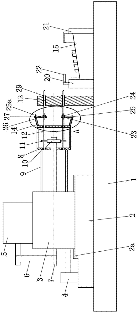
Figure 1 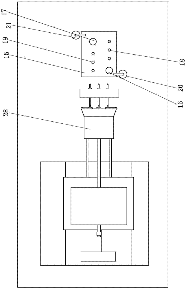
Figure 2 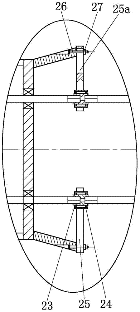
Figure 3
Abstract
Description
technical field
[0001] The invention belongs to the field of automobile exhaust manifold processing, in particular to a drilling method for the small head end of the automobile exhaust manifold. Background technique
[0002] The exhaust manifold is an important part of the exhaust system of the automobile engine. There are 4 mounting holes on its small head end. The axis lines of the 3 mounting holes are parallel and close to each other. The current processing method is to drill holes one by one. This processing method not only has low processing efficiency, but also cannot reliably guarantee the position of the three holes. Therefore, it is urgent to solve the above technical problems. Contents of the invention
[0003] The technical problem to be solved by the present invention is to provide a method for drilling the small end of the exhaust manifold of an automobile, and it is desired to drill three mounting holes at the small end at the same time.
[0004] The technic...
Examples
Embodiment Construction
[0020] Below in conjunction with accompanying drawing and embodiment the present invention will be further described:
[0021] A method for drilling a small head end of an automobile exhaust manifold, characterized in that it comprises the following steps:
[0022] Step a: Set up a drilling tool on the base, such as figure 1 , 2 , 3, the drilling tool is mainly composed of a horizontal base plate 1, a mounting seat 2, a transmission box 3, a driving cylinder 4, a motor 5, a transmission belt 6, a transmission shaft 7, a connection box 8, a horizontal connection column 9, and a large driving gear 10 , driven pinion 11, drive shaft 12, drill bit 13 and conical connecting bucket 14 etc. constitute. Wherein, the horizontal bottom plate 1 is a rectangular plate, and the horizontal bottom plate 1 is fixed on the base (not shown in the drawings) by T-shaped bolts. A mounting base 2 is fixed on the left side of the horizontal base plate 1, and a transmission box 3 is arranged on th...