Vehicle-mounted double-motor power take-off power supply system and method
A technology of a power supply system and power supply method, which is applied in the fields of current collectors, electric vehicles, vehicle components, etc., can solve the problems of too large a single generator body, high vehicle installation space requirements, and low power generation system efficiency, so as to reduce vehicle losses. , the effect of reducing volume and improving efficiency
- Summary
- Abstract
- Description
- Claims
- Application Information
AI Technical Summary
Problems solved by technology
Method used
Image
Examples
Embodiment 1
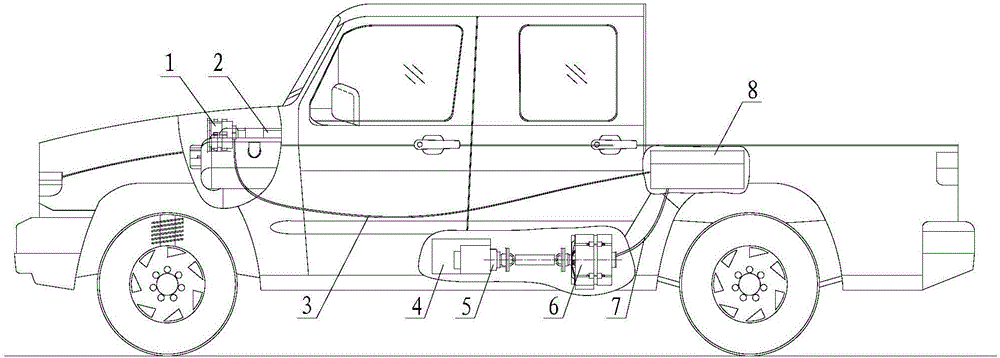
[0037] (1) A low-power generator 1 with a power of 3.5kW is installed in the engine compartment, and it is connected to the crankshaft wheel of the vehicle engine 2 by a belt. The vehicle engine 2 drives the low-power generator 1 to run and generate electricity, and the low-power generator 1 is connected to the control unit 8 through the low-power generator connecting cable 3 .
[0038] (2) A high-power generator 6 with a power of 7.5kW is installed at the vehicle power take-off, and is connected to the vehicle gearbox 4 through the power take-off 5 . The output torque of the power take-off 5 drives the high-power generator 6 to run and generate electricity; and the high-power generator 6 is connected to the control unit 8 through the high-power generator connecting cable 7 .
[0039] (3) When the system is working, if the electric load of the whole vehicle is less than 3.5kW, the control unit 8 will turn on the low-power generator 1 to generate power; if the electric load of ...
Embodiment 2
[0041] (1) A low-power generator 1 with a power of 5kW is installed in the engine compartment, and it is connected to the crank wheel of the vehicle engine 2 by a belt. The vehicle engine 2 drives the low-power generator 1 to run and generate power; and the low-power generator 1 is connected to the control unit 8 through the low-power generator connecting cable 3 .
[0042] (2) The high-power generator 6 of power 10kW is installed in the power take-off port of the vehicle, and it is mutually connected with the vehicle gearbox 4 through the power take-off 5; The output torque of the power take-off 5 drives the high-power generator 6 to run and generate electricity; The power generator 6 is connected to the control unit 8 via a high-power generator connection cable 7 .
[0043](3) When the system is working, if the electric load of the whole vehicle is less than 5kW, the control unit 8 independently turns on the low-power generator 1 to generate electricity; if the electric load...
Embodiment 3
[0045] (1) The low-power generator 1 of power 7.5kW is installed in the engine compartment, and it is interconnected with the crankshaft wheel of vehicle engine 2 by belt, and vehicle engine 2 drives low-power generator 1 to run and generate electricity; And low-power generator 1 passes The low-power generator connecting cable 3 is connected to the control unit 8 with each other.
[0046] (2) A high-power generator 6 with a power of 12kW is installed at the vehicle power take-off, and is connected to the vehicle gearbox 4 through the power take-off 5 . The output torque of the power take-off 5 drives the high-power generator 6 to run and generate electricity; and the high-power generator 6 is connected to the control unit 8 through the high-power generator connecting cable 7 .
[0047] (3) When the system is working, if the electric load of the whole vehicle is less than 7.5kW, the control unit 8 independently turns on the low-power generator 1 to run and generate electricity;...
PUM
 Abstract
Description
Claims
Application Information
 - R&D
- Intellectual Property
- Life Sciences
- Materials
- Tech Scout
- Unparalleled Data Quality
- Higher Quality Content
- 60% Fewer Hallucinations
Browse by: Latest US Patents, China's latest patents, Technical Efficacy Thesaurus, Application Domain, Technology Topic, Popular Technical Reports.
© 2025 PatSnap. All rights reserved.Legal|Privacy policy|Modern Slavery Act Transparency Statement|Sitemap|About US| Contact US: help@patsnap.com

