Fluid kinetic energy conversion device with simulated tail fin swing excitation

A kinetic energy conversion and excitation technology, which is applied in ocean energy power generation, engine components, machines/engines, etc., can solve problems such as unsuitable for large-scale applications, poor environmental adaptability, and limited vibration amplitude, and achieve easy integration and miniaturization , Strong wave energy absorption ability, wide response frequency effect

Active Publication Date: 2017-08-25
HARBIN INST OF TECH
View PDF2 Cites 0 Cited by
  • Summary
  • Abstract
  • Description
  • Claims
  • Application Information

AI Technical Summary

Problems solved by technology

[0006] The present invention aims to solve the problem of limited vibration amplitude, narrow response frequency band, low energy conversion efficiency and low energy utilization rate of the piezoelectric sheet due to the simple use of seawater pressure, which is not suitable for large-scale application and the environment. The problem of poor adaptability, and then provide a fluid kinetic energy conversion device imitating tail fin swing excitation

Method used


Image

  • Fluid kinetic energy conversion device with simulated tail fin swing excitation
  • Fluid kinetic energy conversion device with simulated tail fin swing excitation
  • Fluid kinetic energy conversion device with simulated tail fin swing excitation

Examples


specific Embodiment approach 1

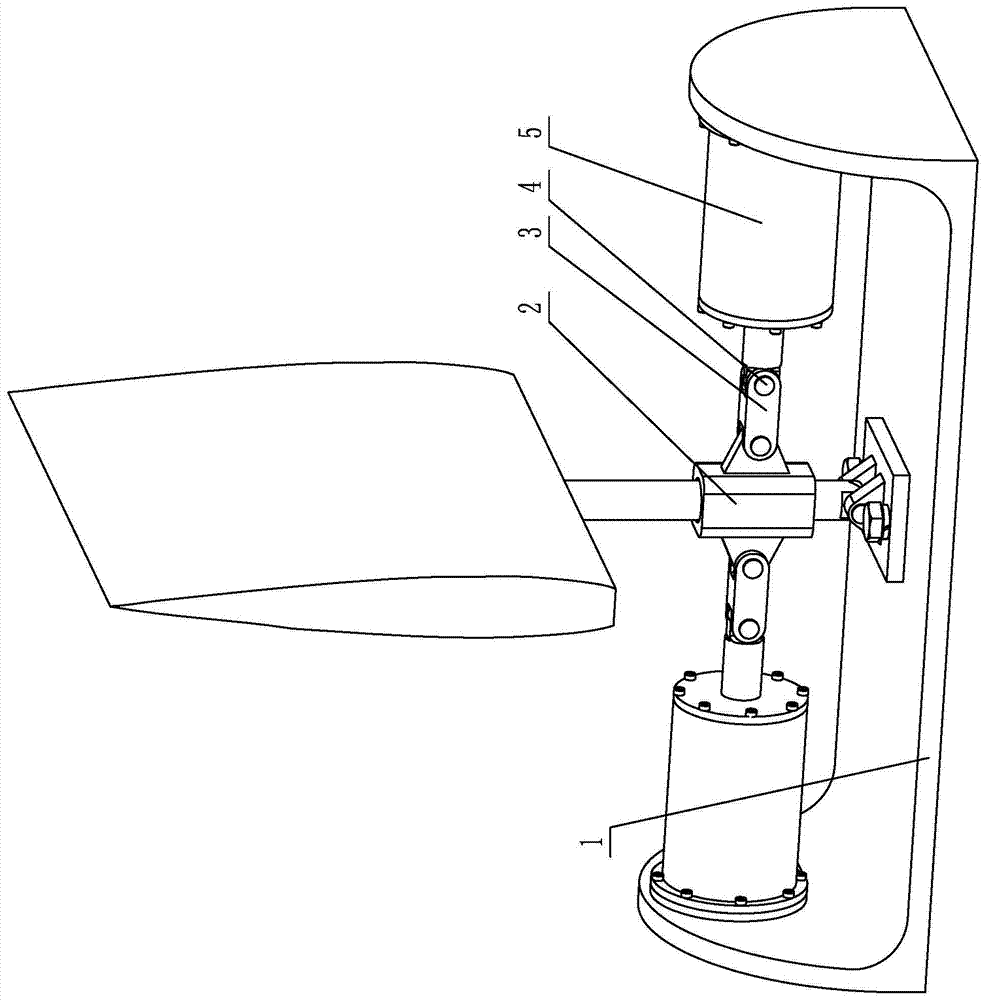
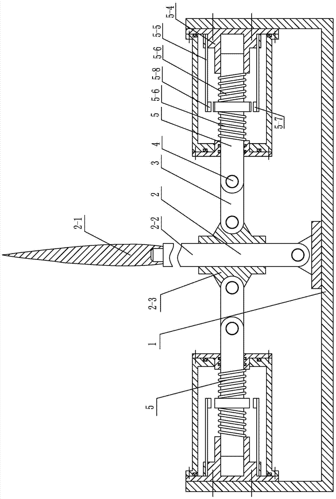
[0013] Specific implementation mode one: combine Figure 1 to Figure 8 To illustrate this embodiment, a fluid kinetic energy conversion device for imitating tail fin swing excitation fluid kinetic energy conversion device in this embodiment includes a base 1, a swing assembly 2, two pull rods 3 and two piezoelectric power generation assemblies 5;

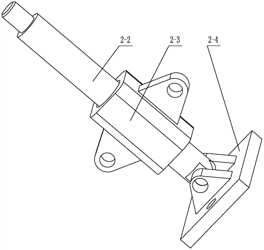
[0014] The swing assembly 2 includes a bionic tail fin 2-1, a swing rod 2-2, a connecting slider 2-3 and a swing rod base 2-4, the swing rod base 2-4 is installed in the middle part of the base 1, and the swing rod 2-2 The lower end is hinged with the swing rod base 2-4, the connecting slider 2-3 is set on the swing rod 2-2, and the bionic caudal fin 2-1 is installed on the upper end of the swing rod 2-2; The pair is set on the base 1;

[0015] Each piezoelectric generating assembly 5 includes a sliding rod 5-1, a permanent magnet seat 5-1-2, a sealing cover 5-2, a casing 5-3, a piezoelectric generating base 5-4, two springs 5-6, ...

specific Embodiment approach 2

[0019] Specific implementation mode two: combination figure 2 It is explained that the base 1 of this embodiment has a U-shaped structure, and the two piezoelectric generating assemblies 5 are arranged on two inner sides of the base 1 facing each other. With such arrangement, the structure is simple, the use is convenient, and the actual needs of different environments can be adapted. Others are the same as in the first embodiment.

specific Embodiment approach 3

[0020] Specific implementation mode three: combination figure 1 with Figure 4 It is explained that the housing 5-3 in this embodiment is a bucket-type housing. With such setting, the processing and use are convenient, and the actual needs are met. Others are the same as in the first or second embodiment.


PUM


Abstract

The invention discloses a fluid dynamic energy conversion device imitating tail fin swing vibration excitation, relates to an energy conversion device and aims to solve the problems that a current wave energy generating device is limited in vibration amplitude, narrow in response frequency band, low in energy conversion efficiency, capable of making a piezoelectric plate deform by purely utilizing seawater pressure, low in energy utilization rate, not suitable for large-scale application and poor in environmental adaptation. The fluid dynamic energy conversion device imitating tail fin swing vibration excitation comprises a base, a swing assembly, two drawbars and two piezoelectric generating assemblies, wherein the swing assembly comprises a bionic tail fin, a swing rod, a connecting slide block and a swing rod base; the swing rod base is mounted on the middle part of the base; the lower end of the swing rod is hinged with the swing rod base; the connecting slide block is arranged on the swing rod in a sleeving mode; the bionic tail fin is mounted at the upper end of the swing rod; the two piezoelectric generating assemblies are oppositely arranged on the base; each two piezoelectric generating assembly comprises a slide rod, a permanent magnet base, a sealing cover, a housing, a piezoelectric generating base, two springs, a plurality of vibration excitation permanent magnets, a plurality of vibration receiving permanent magnets and a plurality of piezoelectric plates. The fluid dynamic energy conversion device imitating tail fin swing vibration excitation is used for energy conversion and power generation.

Description

technical field [0001] The invention relates to an energy conversion device, in particular to a fluid kinetic energy conversion device for imitating tail fin swing and vibration excitation, and belongs to the field of new energy piezoelectric power generation. Background technique [0002] In recent years, with the increasingly serious energy crisis, new energy technologies have received widespread attention. In some remote islands far from the coastline, energy is scarce and material transportation costs are high, resulting in some equipment not working properly, which brings great inconvenience to the life of island residents and platform staff. The ocean is a very huge energy treasure house, among which wave energy has high energy density, abundant reserves, wide distribution range, and is suitable for large-scale development and utilization. According to estimates, the energy contained in sea waves is as high as 5000GW. If it can be collected and utilized, it can not on...

Claims


Application Information

Patent Timeline
Patent Type & Authority Patents(China)
IPC IPC(8): F03B13/14H02N2/18
CPCY02E10/30
Inventor 董帝渤陈维山郝亚强石胜君刘军考侯珍秀
Owner HARBIN INST OF TECH
Why Eureka
Try Eureka