Supercharge Your Innovation With Domain-Expert AI Agents!

Wind wheel structure of downwind wind driven generator

A wind power generator and wind direction technology, applied in the field of wind power generation devices and downwind wind power generation devices, can solve the problems of difficult control of fixed blades, and achieve the effect of simple structure and stable wind wheel structure

Inactive Publication Date: 2015-12-09
中卫市振江电器设备有限公司
View PDF10 Cites 1 Cited by
  • Summary
  • Abstract
  • Description
  • Claims
  • Application Information

AI Technical Summary

Problems solved by technology

[0003] In view of the above problems, the present invention provides a wind rotor structure for downwind wind power generators, which can solve the problem that the fixed blades of downwind wind power generators are difficult to control in the high wind speed section

Method used


Image

  • Wind wheel structure of downwind wind driven generator
  • Wind wheel structure of downwind wind driven generator
  • Wind wheel structure of downwind wind driven generator

Examples


Embodiment Construction

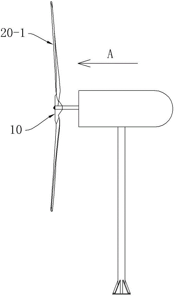
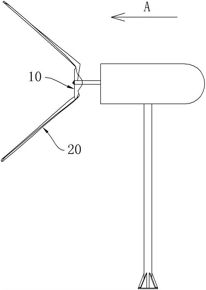
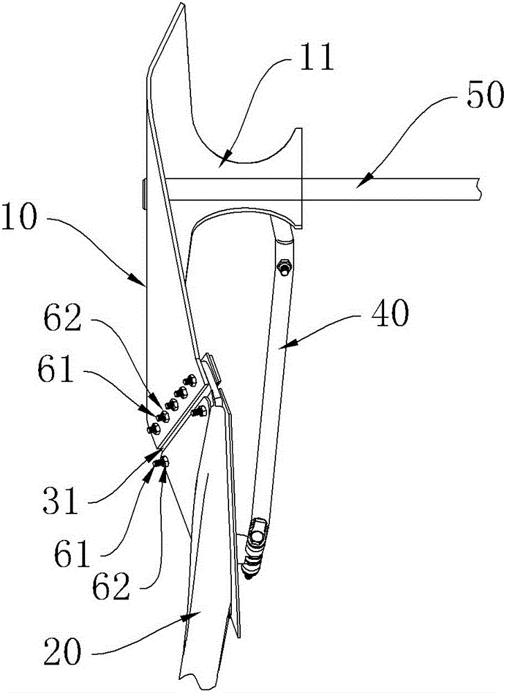
[0021] See figure 2 , image 3 and Figure 4 The impeller structure of the present invention includes a hub 10, blades 20, movable connectors and return springs 40. The hub 10 is mounted on the wheel shaft 50 of the fan through the sleeve part 11 and can drive the wheel shaft 50 to rotate synchronously. The hub 10 and the blades 20 pass through The movable connector is connected in rotation, and the movable connector is an elastic connector 31, see Figure 5 , Figure 6 and Figure 7 The elastic connector 31 includes a hub connecting portion 311 and a blade connecting portion 312, the hub connecting portion 311 and the blade connecting portion 312 are bent at an angle and connected as a whole, and the angle between the hub connecting portion 311 and the blade connecting portion 312 is α, the function of the included angle α is to make the blades have a twist angle after the pitch is changed, and the blades generate resistance during the rotation of the impeller to suppres...


PUM


Abstract

The invention provides a wind wheel structure of a downwind wind driven generator, which can solve the problem of difficult control of fixed blades of a traditional downwind wind driven generator on a high-wind-speed section. The wind wheel structure comprises a hub and blades, wherein the hub is mounted on a wheel shaft of a fan through a shaft sleeve part, and can synchronously rotate with the wheel shaft. The wind wheel structure is characterized in that the hub and the blades are movably connected through a connecting piece; and the movable connecting piece can realize the adjustment of a windward angle and a windward area.

Description

technical field [0001] The present invention relates to the field of wind power generating devices, in particular to the field of downwind wind power generating devices, in particular to the wind rotor structure of the downwind wind power generator. Background technique [0002] At present, in the field of wind power generation, the downwind wind turbines all use fixed blades, see figure 1 , the fixed blade 20-1 is fixed on the hub 10, and the fixed blade 20-1 (see figure 1 ) wind turbines usually adjust the speed and power at high wind speeds through unloading control, short-circuit control, or mechanical brake control, but the above-mentioned control methods have very high requirements on the generator and are easy to damage the generator. If the machine is damaged, it is very likely that there will be speeding and other phenomena, which will cause great hidden dangers to safety. Contents of the invention [0003] In view of the above problems, the present invention pr...

Claims


Application Information

Patent Timeline
IPC IPC(8): F03D1/06F03D7/04
CPCY02E10/72
Inventor 郑国涛赵坤江子安
Owner 中卫市振江电器设备有限公司
Features
  • R&D
  • Intellectual Property
  • Life Sciences
  • Materials
  • Tech Scout
  • Unparalleled Data Quality
  • Higher Quality Content
  • 60% Fewer Hallucinations
Learn More