
Power generation device for highway deceleration strip

A technology for power generation devices and speed bumps, applied to machines/engines, mechanisms that generate mechanical power, mechanical equipment, etc., can solve problems such as low power generation efficiency, influence on opening, and decrease in energy collection density, and achieve higher charging efficiency. Efficiency, the effect of reducing operating frequency

Active Publication Date: 2015-12-09
徐州花千树农业发展有限公司
View PDF5 Cites 18 Cited by
  • Summary
  • Abstract
  • Description
  • Claims
  • Application Information

AI Technical Summary

Problems solved by technology

[0005] At present, similar speed bump power generation devices mainly have the following deficiencies: (1) the existing patents do not "fully utilize the energy generated in the two processes of the speed bump up and down and store and collect the energy of the vehicle passing through the speed bump. Time to release" These two problems are coordinated and solved, resulting in low power generation efficiency
(2) For the generator, when the rotation speed is lower than the minimum rotation speed of the generator, the energy collection continues at this time, which affects the opening of the next energy recovery process on the one hand, and on the other hand affects the efficiency of the generator due to the low rotation speed
Combining these two factors, if the generator speed is too slow, the energy collection density will decrease and the battery charging efficiency will decrease.

Method used


Image

  • Power generation device for highway deceleration strip
  • Power generation device for highway deceleration strip

Examples


Embodiment Construction

[0026] The present invention will be further described below in conjunction with the accompanying drawings and specific embodiments, but the protection scope of the present invention is not limited thereto.

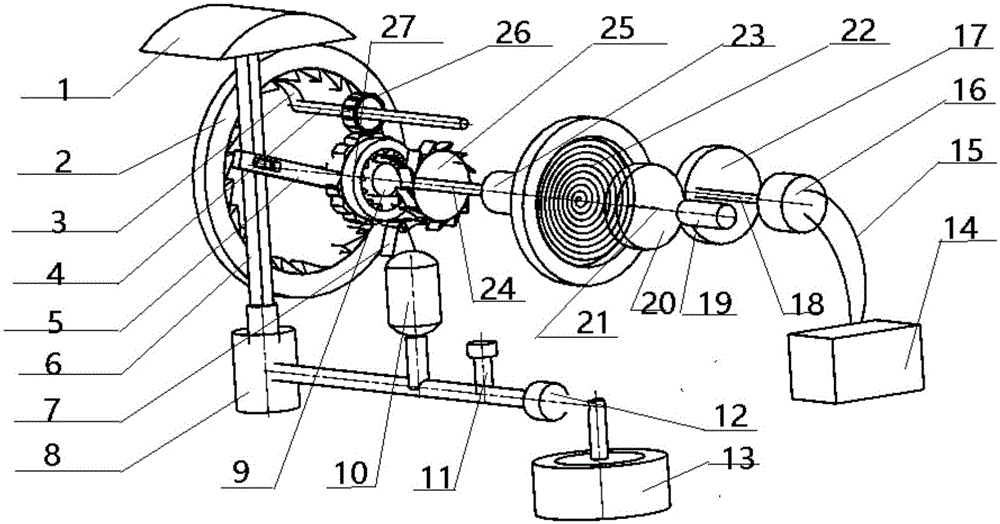
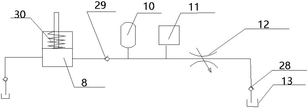
[0027] Such as figure 1 As shown, a road deceleration belt power generation device according to the present invention is characterized in that it includes a mechanical transmission part and a hydraulic control part. The mechanical transmission part includes a deceleration belt 1 fixed on the road surface, a first straight rod 6 fixedly connected to the lower surface of the deceleration belt 1 at one end, a second straight rod 5 hinged at the middle of the first straight rod 6 at one end, and a second shaft 24. The first axis 4 and the third axis 21. Specifically, in this embodiment, the middle part of the first straight rod 6 is provided with a cylindrical protrusion, and the end of the second straight rod 5 is provided with an oblong hole, and the cylindrical protrusion...


PUM


Abstract

The invention relates to a power generation device for a highway deceleration strip. The power generation device comprises the deceleration strip, a first straight rod connected with the deceleration strip, a second straight rod hinged to the first straight rod, a first shaft, a second shaft, a third shaft, a hydraulic cylinder, an energy accumulator, a pressure sensor, an electromagnetic flow control valve and a hydraulic oil tank; the second shaft is sequentially provided with a first ratchet wheel, a first gear, a second detent and a second ratchet wheel, and the first shaft is provided with a first detent which is internally meshed with the first ratchet wheel and a second gear which is externally meshed with the first gear; a clutch is arranged between the second shaft and the third shaft, and the third shaft is provided with a planar volute spring, a one-way gear and a rotation speed sensor; the one-way gear is meshed with a third gear which is connected with an electric generator; the pressure sensor and the rotation speed sensor are electrically connected with the clutch, and the rotation speed sensor is electrically connected with the electromagnetic flow control valve. According to the power generation device for the highway deceleration strip, energy of the deceleration strip is bidirectionally recovered by applying the one-way driving characteristic of the ratchet wheels, a hydraulic system is utilized to control the energy releasing time of the volute spring, and the purpose of saving the energy is achieved.

Description

technical field [0001] The invention relates to a power generation device utilizing the vibration energy of a vehicle, in particular to a power generation device for a road deceleration belt. Background technique [0002] At present, in road sections and places where vehicles are relatively concentrated, in order to reduce traffic accidents and limit vehicle speeds, a number of speed reduction belts are mostly set on the road surface to reduce vehicle speed. Ordinary speed bumps are fixed on the road. Although the vehicle can achieve the purpose of deceleration when passing the speed bump, it consumes some extra energy of the car and brings unnecessary energy waste. [0003] In order to use speed bumps to recover the vibration energy of vehicles, there are currently some invention patents for road speed bump power generation devices. For example, the publication number CN101285455, a road deceleration belt power generation device, includes an upper platen, an upper base pla...

Claims


Application Information

Patent Timeline
IPC IPC(8): F03G7/00
Inventor 何仁许旸
Owner 徐州花千树农业发展有限公司
Learn More