
An Adaptive Calibration Method of Infrared Focal Plane Array with Variable Integration Time

A technology of infrared focal plane and integration time, which is applied in the field of infrared imaging, can solve problems such as unsatisfactory correction effects, and achieve the effects of small error, improved uniformity, and high correction accuracy

Active Publication Date: 2018-05-01
BEIJING RES INST OF SPATIAL MECHANICAL & ELECTRICAL TECH
View PDF3 Cites 0 Cited by
  • Summary
  • Abstract
  • Description
  • Claims
  • Application Information

AI Technical Summary

Problems solved by technology

However, the existing method only weakens the influence of modifying the integration time on the non-uniformity of the pixel by correcting the integration time in sections. However, since the non-uniformity of the output circuit of each detection unit to the integration time still exists, the correction effect is not very ideal.

Method used


Image

  • An Adaptive Calibration Method of Infrared Focal Plane Array with Variable Integration Time
  • An Adaptive Calibration Method of Infrared Focal Plane Array with Variable Integration Time
  • An Adaptive Calibration Method of Infrared Focal Plane Array with Variable Integration Time

Examples


Embodiment

[0106] At different temperatures, the integration time was modified, and the residual amount of image non-uniformity was tested before calculation and correction, after correction by the existing correction method and after correction using the method of the present invention. The test results are shown in Tables 1 to 3. Among them, Table 1 is the statistical table of the non-uniformity residual amount of the original image before correction, Table 2 is the statistical table of the non-uniformity residual amount after correction by the existing method, and Table 3 is the correction value of the present invention. Post-inhomogeneity residual statistical table;

[0107] Table 1

[0108] T / Int

0.1

1

2

4

6

10

15

20

0.0646

0.0920

0.1403

0.0946

0.0984

0.0978

0.0721

22

0.0653

0.0886

0.1318

0.0904

0.0938

0.0941

0.0685

27

0.0667

0.0829

0.1149

0.0847

0.0883

0.0885

0.0637

...


PUM


Abstract

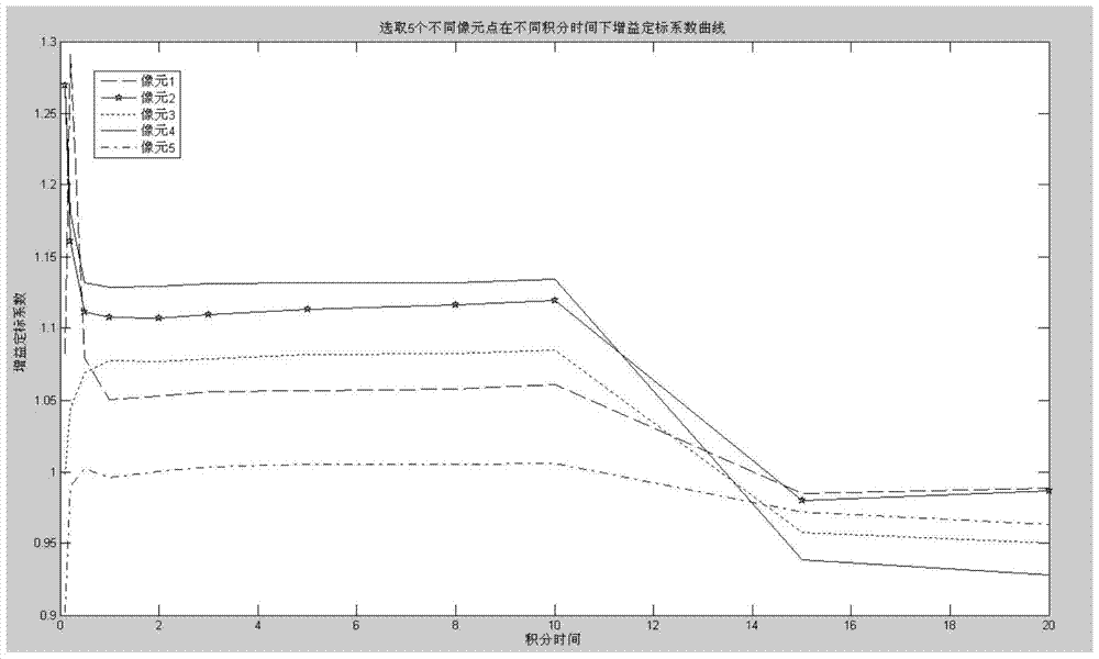
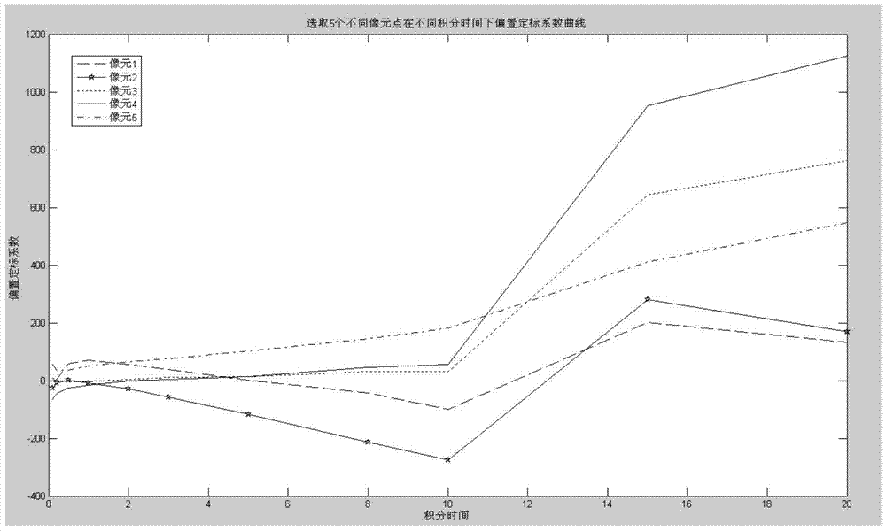
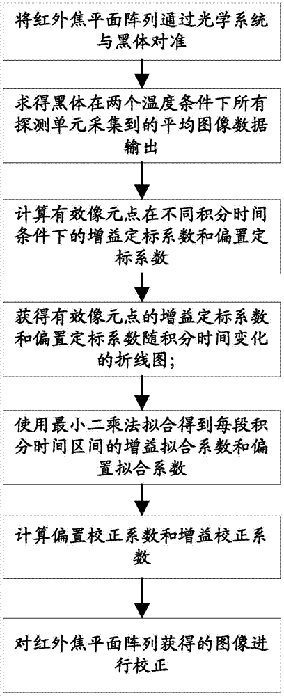
An adaptive correction method under the variable integration time of infrared focal plane arrays, first setting the integration time of different infrared focal plane arrays, using the two-point temperature calibration method to calculate the average image data output collected by the detection unit; obtain each The corresponding gain scaling coefficients and offset scaling coefficients of the effective pixel points under different integration time conditions; then draw the polylines of the gain scaling coefficients and offset scaling coefficients of each effective pixel point changing with the integration time respectively Figure; use the least squares method to fit the gain fitting coefficient and bias fitting coefficient of each integration time interval; finally calculate the bias correction coefficient and gain correction coefficient, and correct the image obtained by the infrared focal plane array, the present invention Since the correction coefficient corresponds to the integration time one by one, the influence of the change of the integration time on the uniformity of the focal plane array is separated. Not only the uniformity of the infrared image is greatly improved, but also the uniformity of the image is not affected by modifying the integration time.

Description

technical field [0001] The invention relates to an infrared focal plane array adaptive correction method, in particular to an infrared focal plane array adaptive correction method under variable integration time, belonging to the technical field of infrared imaging. Background technique [0002] The integration time refers to the time when the infrared focal plane array detection unit generates and accumulates charges when it receives external radiation. For infrared focal plane array imaging systems, physical parameters such as output voltage, responsivity, noise, and specific detection rate are closely related to integration time. Appropriate integration time can improve the overall performance of the system, otherwise, it can inhibit system performance. [0003] In the practical application of the staring infrared focal plane imaging system, it is often necessary to modify the detector integration time according to the target infrared radiation intensity. After correctin...

Claims


Application Information

Patent Timeline
Patent Type & Authority Patents(China)
IPC IPC(8): G01J5/00
Inventor 张守荣王华张大鹏张旭刘涛潘卫军
Owner BEIJING RES INST OF SPATIAL MECHANICAL & ELECTRICAL TECH
Learn More