
Polarizing element or polarizing plate for display device with blue light emitting element

A polarizing element and polarization technology, which is applied in the field of polarizing elements or polarizers for organic electroluminescence, and can solve problems such as low transmittance, poor durability of iodine-based polarizers, and reduced brightness

Active Publication Date: 2017-12-08
NIPPON KAYAKU CO LTD +1
View PDF37 Cites 0 Cited by
  • Summary
  • Abstract
  • Description
  • Claims
  • Application Information

AI Technical Summary

Problems solved by technology

Among them, dye-based polarizers are characterized by high heat resistance, high humidity and heat durability, high stability, and high color selectivity by mixing. On the other hand, they have the following problems: When comparing polarizers, the transmittance, that is, the contrast is lower than that of iodine-based polarizers
However, the transmittance of such iodine-based polarizers is 35% to 44%, so there is a problem that the brightness is greatly reduced
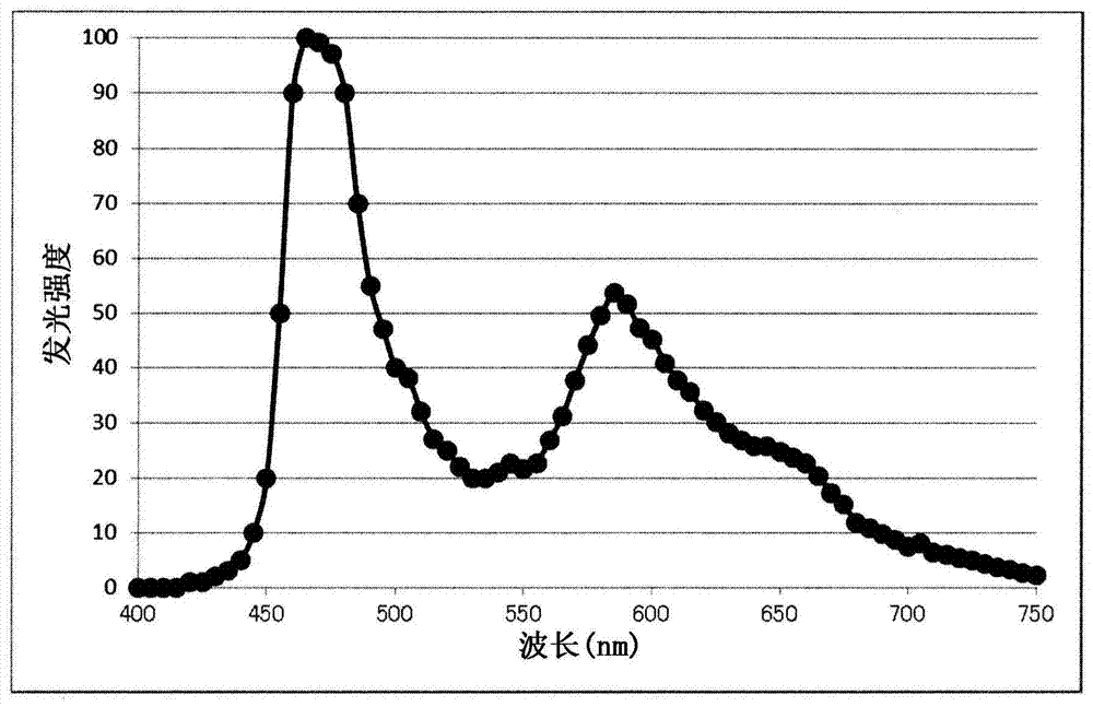
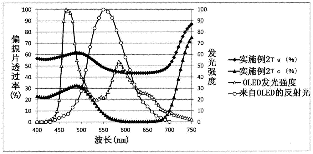
Furthermore, it absorbs more light of 400nm to 500nm belonging to the short-wavelength side of visible light, so for example, the OLEDs described in Patent Document 3 and Patent Document 4, and the blue luminous efficiency of OLEDs that have strong light emission near 460 nm decrease, Therefore, the brightness is reduced and the color display is insufficient
In response to such a large decrease in luminance, it is considered that the use of an iodine-based polarizer with a transmittance of 45% to 60% can prevent the decrease in luminance, but the durability of the iodine-based polarizer is poor, and long-term use will eventually lead to a decrease in luminance , so the reliability is obviously insufficient

Method used


Image

  • Polarizing element or polarizing plate for display device with blue light emitting element
  • Polarizing element or polarizing plate for display device with blue light emitting element
  • Polarizing element or polarizing plate for display device with blue light emitting element

Examples


example 1

[0113] [chemical formula 12]

[0114]

[0115] [Compound Example 2]

[0116] [chemical formula 13]

[0117]

[0118] [Compound Example 3]

[0119] [chemical formula 14]

[0120] [Compound Example 4]

[0121] [chemical formula 15]

[0122]

[0123] [Compound Example 5]

[0124] [chemical formula 16]

[0125]

[0126] Next, more specific examples of the azo compound represented by formula (2) will be shown in the form of the following free acid.

[0127] [Compound Example 6]

[0128] [chemical formula 17]

[0129]

[0130] [Compound Example 7]

[0131] [chemical formula 18]

[0132]

[0133] [Compound Example 8]

[0134] [chemical formula 19]

[0135]

[0136] [Compound Example 9]

[0137] [chemical formula 20]

[0138]

[0139] [Compound Example 10]

[0140] [chemical formula 21]

[0141]

example 11

[0143] [chemical formula 22]

[0144]

[0145] [Compound Example 12]

[0146] [chemical formula 23]

[0147]

[0148] [Compound Example 13]

[0149] [chemical formula 24]

[0150] [Compound Example 14]

[0151] [chemical formula 25]

[0152]

[0153] Next, more specific examples of the azo compound represented by formula (3) will be shown in the form of the following free acid.

[0154] [Compound Example 15]

[0155] [chemical formula 26]

[0156]

[0157] [Compound Example 16]

[0158] [chemical formula 27]

[0159]

[0160] [Compound Example 17]

[0161] [chemical formula 28]

[0162]

[0163] [Compound Example 18]

[0164] [chemical formula 29]

[0165]

[0166] [Compound Example 19]

[0167] [chemical formula 30]

[0168]

[0169] [Compound Example 20]

[0170] [chemical formula 31]

[0171]

[0172] [Compound Example 21]

[0173] [chemical formula 32]

[0174]

[0175] [Compound Example 22]

[0176] [chemical formula 33] ...

Embodiment 1

[0270] A polyvinyl alcohol film (VF-XS manufactured by Kuraray Co., Ltd.) with an average degree of polymerization of 99% or higher and an average degree of polymerization of 2400 was soaked in warm water at 45° C. for 2 minutes, subjected to swelling treatment, and stretched to 1.30 times. The swelling-treated film was soaked in an aqueous solution at 45° C. containing 1500 parts by weight of water, 1.5 parts by weight of sodium tripolyphosphate, and 0.15 parts by weight of the dye described in Example 2 of JP-A-09-132726, and dyed. Stretching treatment was performed for 5 minutes in a 50° C. aqueous solution containing 30.0 g / L of boric acid while stretching the dyed film 5.0 times. Keep the tense state of the film obtained by the boric acid treatment, and wash in water at 30°C for 20 seconds, and dry the obtained film at 70°C for 9 minutes to obtain a transmittance of about 50% according to the present invention. the polarizing element. The dried polarizing element and an ...


PUM


Abstract

[Problem] The present invention relates to a polarizing element and a polarizing plate, which can improve contrast and enhance color display characteristics in an organic electroluminescent display device. [Solution] A substrate having a polarizing function and containing an azo compound is controlled such that the substrate alone has a transmittance of 45% to 60%, the average transmittance of 440-nm to 500-nm wavelengths for one substrate is 50% or more, and the average transmittance of 550-nm to 650-nm wavelengths as obtained by measuring two substrates arranged such that the absorption axis directions thereof are orthogonal to one another is 10% or less.

Description

technical field [0001] The present invention relates to a polarizing element or a polarizing plate for organic electroluminescence. Background technique [0002] A polarizing element is generally produced by adsorbing and aligning iodine as a dichroic dye or a dichroic dye on a polyvinyl alcohol resin film. On at least one side of the polarizing element, a protective film made of triacetyl cellulose or the like is attached via an adhesive layer to form a polarizing plate, which is used in a liquid crystal display device or the like. A polarizing plate using iodine as a dichroic dye is called an iodine-based polarizing plate, and a polarizing plate using a dichroic dye as a dichroic dye is called a dye-based polarizing plate. Among them, dye-based polarizers are characterized by high heat resistance, high humidity and heat durability, high stability, and high color selectivity by mixing. On the other hand, they have the following problems: When comparing polarizing plates, ...

Claims


Application Information

Patent Timeline
Patent Type & Authority Patents(China)
IPC IPC(8): G02B5/30C09B31/072C09B31/22C09B33/10C09B45/28H01L51/50H05B33/02
CPCC09B31/072C09B31/22C09B33/10C09B45/28C09B56/16C09B67/0055G02B5/3025
Inventor 望月典明
Owner NIPPON KAYAKU CO LTD
Learn More