Low-temperature plasma deodorization device

A technology of low-temperature plasma and isolation barrier, which is applied in deodorization, separation methods, and separation of dispersed particles, etc. It can solve the problems of inconvenient disassembly and maintenance, lack of protection devices, and reduced device efficiency, so as to achieve convenient and regular cleaning and maintenance and ensure safety. , The effect of convenient maintenance

Inactive Publication Date: 2015-12-16
李宇花
View PDF6 Cites 7 Cited by
  • Summary
  • Abstract
  • Description
  • Claims
  • Application Information

AI Technical Summary

Problems solved by technology

[0002] In some places such as garbage disposal and public toilets, there will be obvious odors, which can easily cause people's discomfort, and the gases that cause these problems are mostly methyl mercaptan, ammonia, hydrogen sulfide and some ethers. In the past, people mostly used Some chemical substances are used to oxidize these substances to eliminate peculiar smell. Many plasma deodorization devices have appeared in the prior art, and most of them pass high voltage to the plate to generate a high-voltage electric field and generate a large number of positive and negative ions with strong oxidizing properties, thereby eliminating odor. smell, but the plates of this technology are smooth plates, and the voltage that needs to be applied needs to be very high, which will consume a lot of energy, and it is not safe to operate with high voltage. Most of these plates are bare, and in some humidity In a very large environment, the effect will be very poor, and there is no filter device, some large particles in the air will enter between the plates, which will also reduce the efficiency of the device. Some devices are only operated by some switches, which is very unintelligent. , and it is very inconvenient to disassemble and overhaul. Most of the equipment lacks protective devices, which are prone to accidents and cause danger.

Method used


Image

  • Low-temperature plasma deodorization device
  • Low-temperature plasma deodorization device
  • Low-temperature plasma deodorization device

Examples


Embodiment Construction

[0023] The following will clearly and completely describe the technical solutions in the embodiments of the present invention with reference to the accompanying drawings in the embodiments of the present invention. Obviously, the described embodiments are only some, not all, embodiments of the present invention. Based on the embodiments of the present invention, all other embodiments obtained by persons of ordinary skill in the art without making creative efforts belong to the protection scope of the present invention.

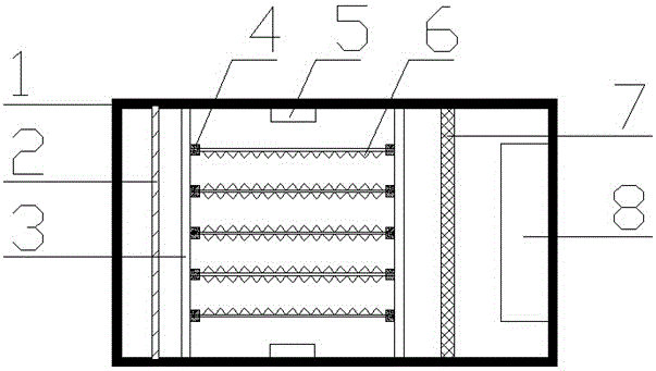
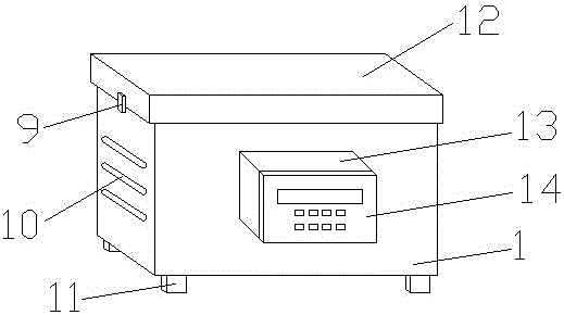
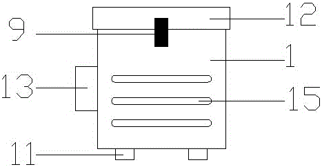
[0024] see Figure 1~3 , a low-temperature plasma deodorization device, including a casing 1, an isolation grid plate 2, an insulating support 3, a fixed block 4, a transmitter box 5, a discharge electrode plate 6, an air filter 7, a blower 8, a buckle 9, and an outlet Air outlet 10, box leg 11, shell cover 12, distribution box 13, operation panel 14 and air inlet 15, described box leg 11 is fixed on the bottom of shell 1, and described air outlet 10 is arrang...


PUM


Abstract

The invention discloses a low-temperature plasma deodorization device, which comprises a housing, an isolating grid plate, an insulating bracket, a fixed block, a transmitter box, discharge pole plates, an air filter net, an air feeder, a buckle, an air outlet, box legs, a shell cover, a distribution box, an operation panel and an air inlet. The low-temperature plasma deodorization device has the beneficial effects that the surfaces of the discharge pole plates are in a sharp sawtooth shape, so that a non-uniform electric field is generated between the two pole plates; and the required voltage is relatively small when the same discharge effect is generated. A polyethylene insulating material coats each discharge pole plate, so that the discharge pole plates are not exposed in moist air in a few of places with relatively high humidity, so as to ensure the discharge effect. The isolating grid plate is arranged between the discharge pole plates and the air outlet and is detachable, so that a few of electric arcs and the like generated during discharging are prevented from contacting the outside. Switches in the distribution box are contactors, so that control on high voltage through low voltage can be achieved; and the risk caused by direct contact on the high voltage is avoided.

Description

technical field [0001] The invention relates to a plasma deodorization device, in particular to a low-temperature plasma deodorization device, which belongs to the field of plasma deodorization equipment. Background technique [0002] In some places such as garbage disposal and public toilets, there will be obvious odors, which can easily cause people's discomfort, and the gases that cause these problems are mostly methyl mercaptan, ammonia, hydrogen sulfide and some ethers. In the past, people mostly used Some chemical substances are used to oxidize these substances to eliminate peculiar smell. Many plasma deodorization devices have appeared in the prior art, and most of them pass high voltage to the plate to generate a high-voltage electric field and generate a large number of positive and negative ions with strong oxidizing properties, thereby eliminating odor. smell, but the plates of this technology are smooth plates, and the voltage that needs to be applied needs to be...

Claims


Application Information

Patent Timeline
Patent Type & Authority Applications(China)
IPC IPC(8): A61L9/22B01D53/32
Inventor 李宇花
Owner 李宇花
Why Eureka
Try Eureka