
Paint mist capturing device and process for spray booth

A paint spray booth and paint mist technology, which is applied to spraying devices, devices for coating liquid on the surface, coatings, etc., can solve the problems of large environmental protection treatment load of organic waste gas, limited paint mist capture ability, and short service life of equipment, etc. Achieve the effect of small investment, long service life and small investment in equipment

Active Publication Date: 2015-12-16
天津奥展化工科技有限公司
View PDF4 Cites 3 Cited by
  • Summary
  • Abstract
  • Description
  • Claims
  • Application Information

AI Technical Summary

Problems solved by technology

[0004] Most of the current spray booths use vertical water curtains, and use circulating water containing chemicals to form water curtains on the surface of the vertical water curtains to capture excess paint mist, so as to separate VOC from paint mist, and then carry out environmental protection respectively. However, the existing technology has limited ability to capture paint mist, and the capture rate is low. This will cause the paint mist to be carried out by the gas, and the subsequent environmental protection treatment of organic waste gas will have a large load. At the same time, a large amount of waste water will be generated, which needs to be equipped with sewage treatment. Facilities, many civil engineering foundations, large investment, difficult maintenance, high operating costs, difficult to meet the needs of environmental protection and clean production, and short service life of equipment

Method used


Image

  • Paint mist capturing device and process for spray booth
  • Paint mist capturing device and process for spray booth

Examples


Embodiment Construction

[0020] The technical solution of the present invention will be further described in detail below in conjunction with the accompanying drawings and specific embodiments, and the described specific embodiments are only for explaining the present invention, and are not intended to limit the present invention.

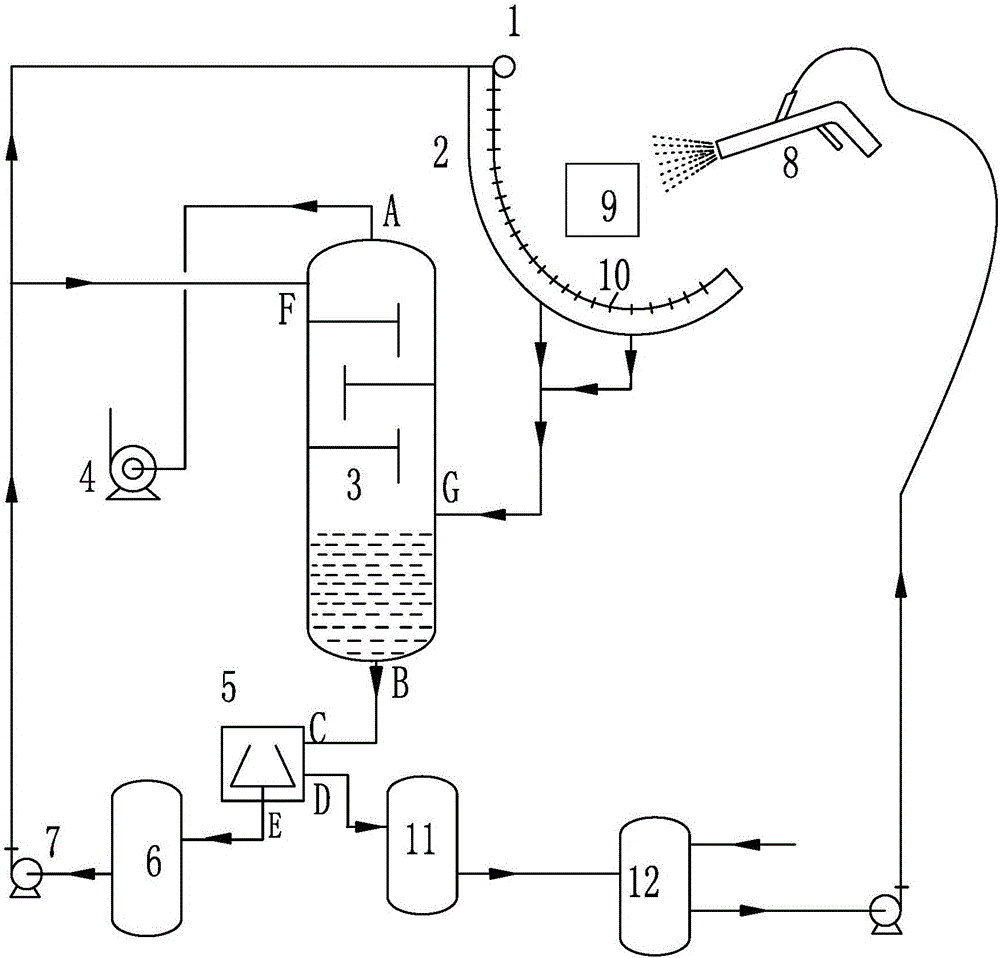
[0021] Such as figure 1 and figure 2 As shown, a paint mist capture device for a spray booth of the present invention includes a spray gun 8 arranged in the spray booth, a raw paint tank 12, a solvent storage tank 6, a recycled paint storage tank 11 and a separation tower 3, the raw paint tank 12 and the connecting pipeline between the spray gun 8 is provided with a pump; in order to make gas and liquid flow smoothly into the separation tower 3, the top air inlet of the separation tower 3 is connected with a blower fan 4, and the separation tower 3 adopts a plate type Tower, preferably a plate tower with a vertical sieve tray structure, the number of trays in the separat...


PUM


Abstract

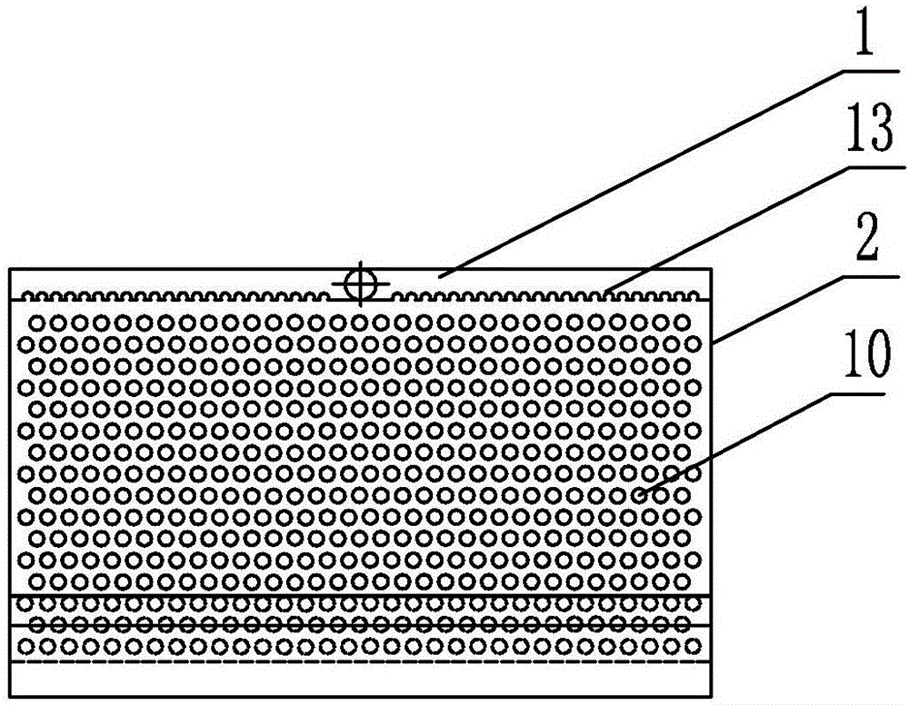
The invention discloses a paint mist capturing device for a spray booth. The paint mist capturing device comprises a spray gun, a raw material paint tank, a solvent storage tank, a recycled paint storage tank and a separation tower, all of which are arranged in the spray booth. The separation tower is connected with an exhaust opening of a draught fan, a centrifugal machine, the solvent storage tank and a collection groove. The centrifugal machine is connected with the paint storage tank and the solvent storage tank. Multiple spray holes are evenly distributed in a solvent spraying pipe in the axial direction. A collection groove with the arc bottom face is formed below the solvent spraying pipe. The width of the collection groove is equal to the length of the solvent spraying pipe. An interlayer pore plate equidistant with the bottom face is arranged in the collection groove. An interlayer space is formed below the interlayer pore plate. The bottom face of the collection groove is provided with multiple liquid discharge holes connected to the separation tower through connection pipes. In the processing process, solvents are separated from captured paint through the centrifugal machine, the solvents are recycled, the separated paint can be recycled continuously, the loss is reduced, and the cost spent on waste water treatment is saved. The paint mist capturing device is convenient to maintain, low in investment, good in operation state and long in service life.

Description

technical field [0001] The invention relates to a technique for capturing paint mist in a spray booth. In particular, it relates to an environmentally friendly process for capturing high-efficiency paint mist in a spray booth, and belongs to the field of environmental protection technology. Background technique [0002] The spray booth is the key equipment necessary for the painting workshop. It is a room dedicated to painting operations and is widely used in industries such as automobiles, furniture, and packaging. In the painting process, its structure and equipment are complicated. The existing spray booths generally include water curtain spray booths, water wash spray booths, oil wash spray booths, pumpless spray booths, and water cyclone spray booths. [0003] The spray booth is a closed space, which can prevent the spray residue from escaping to the outside world. The spray residue in the spray booth will form a high-density and high-concentration state after long-ter...

Claims


Application Information

Patent Timeline
Patent Type & Authority Applications(China)
IPC IPC(8): B05B15/12B05B15/04
CPCY02P70/10
Inventor 张兵朱艳安喜报李建明阮杰
Owner 天津奥展化工科技有限公司
Learn More