
A Punch Manipulator for Reprocessing Rotor Punching

A technology of rotor punching and manipulators, applied in manipulators, metal processing equipment, manufacturing tools, etc., can solve the problems of inability to determine the quantity of feed materials, many pauses, etc., and achieve the effect of high yield and simple operation

Inactive Publication Date: 2017-03-29
NANCHANG HANGKONG UNIVERSITY
View PDF5 Cites 0 Cited by
  • Summary
  • Abstract
  • Description
  • Claims
  • Application Information

AI Technical Summary

Problems solved by technology

[0004] The purpose of the present invention is to provide a punch manipulator for rotor punching and reprocessing, which overcomes the shortcomings of the rotor punching and reprocessing manipulators in the market that stop frequently and cannot determine the quantity of incoming materials

Method used

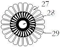

Image

  • A Punch Manipulator for Reprocessing Rotor Punching
  • A Punch Manipulator for Reprocessing Rotor Punching
  • A Punch Manipulator for Reprocessing Rotor Punching

Examples


Embodiment Construction

[0023] The present invention will be described in detail below in conjunction with the accompanying drawings and specific examples.

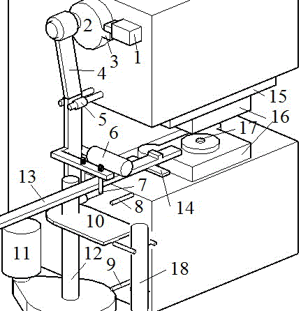
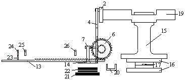
[0024] Transmission device of the present invention such as figure 2 As shown, the connection diagram of each part is shown in Figure 3-Figure 4 As shown: the punch slider 15 is connected to the main rotating shaft 19 and the upper half of the mold 16, the brake wheel 2 is located at the left end of the main rotating shaft 19, the transmission rod 4 is connected to the brake wheel 2, and the permanent magnet sucker is located on a branch of the transmission rod 4 , the branch of the permanent magnetic sucker 7 and the transmission rod 4 is not completely fixed, but has a certain range of motion up and down, such as image 3 and Figure 4 As shown, when the main rotating shaft 19 rotates, it drives the slider 15 and the mold 6 to move up and down, and simultaneously the transmission rod 4 and the permanent magnet sucker 7 also move up and dow...


PUM


Abstract

The invention discloses a punching machine manipulator for reprocessing rotor punching sheets. The manipulator mainly includes mechanical transmission, material feeding and quantity determination, parameter adjustment, control and other parts. The kinetic energy of the manipulator is obtained from the brake wheel of the punch through the transmission rod, and the feeding rod is driven to move left and right to send the raw material to the mold for processing. The judgment circuit judges the quantity of a single feeding, and controls the operation of the punch with the cooperation of the control system. Protect the mold; the parameter adjustment part mainly adjusts various parameters when the manipulator is running. The invention has the advantages that: the system can realize the reprocessing of the rotor silicon steel sheet under the condition that the punch press does not work intermittently, and has the characteristics of high efficiency, safety and high yield.

Description

technical field [0001] The invention designs a punching machine manipulator used for reprocessing rotor punching sheets, in particular relates to a punching machine manipulator which uses double suction cups to absorb raw materials and uses a judging device to judge the quantity of feed materials. Background technique [0002] Punching machine is an essential process equipment for stamping processing, and it is a necessary machine for motor stator and rotor processing. The existing stamping factories in China, especially small and medium-sized enterprises, still produce independently with one person and one machine. This method is inefficient and has a high risk factor. Some existing manipulators cannot work continuously, and the press is in idle state for more than 75% of the time. [0003] In the process of punching the stator and rotor silicon steel sheet of the motor, usually the stator silicon steel sheet is punched by the punching machine at one time, while the rotor...

Claims


Application Information

Patent Timeline
Patent Type & Authority Patents(China)
IPC IPC(8): B25J11/00B21D43/18
Inventor 任尚坤周留赐
Owner NANCHANG HANGKONG UNIVERSITY
Learn More