Continuous running power generation device of electric vehicle

A technology for power generation devices and electric vehicles, which is applied in the fields of mechanics and electricity, and can solve the problems of limited electric energy storage, insufficient combustion, and air pollution in electric vehicles.

Inactive Publication Date: 2015-12-16
周勇
View PDF10 Cites 2 Cited by
  • Summary
  • Abstract
  • Description
  • Claims
  • Application Information

AI Technical Summary

Problems solved by technology

[0002] At present, most of the power used in the automobile industry uses gasoline engines or diesel engines as power devices. Due to insufficient combustion of gasoline or diesel, exhaust gas will be generated during driving, which will pollute

Method used


Image

  • Continuous running power generation device of electric vehicle
  • Continuous running power generation device of electric vehicle
  • Continuous running power generation device of electric vehicle

Examples


Embodiment 1

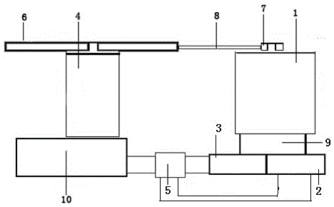
[0020] Example 1, such as figure 1 Shown: a power generation device for continuous driving of an electric vehicle, including a vehicle drive motor 4, a generator 1, a first energy storage device 2, a second energy storage device 3, a bidirectional thyristor potential relay switch 5, and power transmission facilities , the charger 9 and the inverter 10; the vehicle drive motor 4 is connected to the generator 1 through the power transmission facility, and the generator 1 is connected to the first energy storage device 2 and the second energy storage device 3 respectively through the charger 9, and the first energy storage device 3 The energy storage device 2 and the second energy storage device 3 are respectively connected to the bidirectional thyristor potential relay switch 5 , and the bidirectional thyristor potential relay switch 5 is connected to the vehicle drive motor 4 through the inverter 10 .

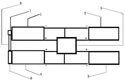
[0021] see figure 2 : The positive pole and negative pole of the first en...

Embodiment 2

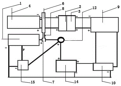
[0023] Embodiment 2, this embodiment is an application example of the applicant. see image 3 : On the basis of Embodiment 1, this embodiment adds a voltage intelligent regulator 15. The negative pole of the voltage intelligent mediator 15 is connected to the negative pole of the 12V inverter 10, the negative pole of the 12V battery 14, and the negative pole of the generator 1; The positive and negative poles of the 12V storage battery 14 are correspondingly connected to the positive and negative poles of the 12V inverter 10; the vehicle starting power switch 12 and the 12V storage battery 14 are existing parts of the vehicle.

[0024] see image 3 : We install a 2500W90A12V generator 1 on an electric tricycle with a power of 800W, charge the 12V battery 14 through an intelligent mediator 15, and invert the 12V voltage of the charger 9 into 220V or higher through a 12V inverter 10 The voltage is charged to the 60V first accumulator 2 through the fast charger, and at the sam...

Embodiment 3

[0026] Embodiment 3. The power transmission facility of this embodiment adopts a gear gearbox. In order to distinguish it from the vehicle drive gearbox in the prior art, the gear gearbox is integrated into a power generation gearbox 13 .

[0027] Since the large belt pulley 6 is directly installed on the central shaft of the vehicle drive motor 4, the resulting motor resistance is too large, so the power transmission facility is designed as a power generation gearbox 13 to reduce the resistance of the electric vehicle during power generation during operation and increase the speed of the vehicle. Stability of running power generation.

[0028] Such as Figure 7 As shown: the vehicle drive motor 4 is connected to the vehicle drive gearbox 32, the vehicle drive gearbox 32 is installed at the center of the vehicle half shaft 23, the other end of the vehicle drive motor 4 is connected to the power generation gearbox 13, and the other end of the power generation gearbox 13 is conn...


PUM


Abstract

A continuous running power generation device of an electric vehicle comprises a vehicle driving motor and further comprises a power generator, a first energy storage device, a second energy storage device, a both-way silicon controlled rectifier potential relay switch, a power transmission facility, a charger and an inverter. The vehicle driving motor is connected with the power generator through the power transmission facility. The power generator is connected with the first energy storage device and the second energy storage device through the charger. The first energy storage device and the second energy storage device are connected with the both-way silicon controlled rectifier potential relay switch. The both-way silicon controlled rectifier potential relay switch is connected with the vehicle driving motor through the inverter. The continuous running power generation device can be applied to urban trams, electric vehicles running on an expressway and other electric vehicles which move on the ground and are driven by electric energy, and can also be applied to small ships in the ocean. The continuous running power generation device has the main beneficial effects of not discharging dirt and being friendly to the environment.

Description

technical field [0001] The invention belongs to the technical field of machinery and electricity, in particular to a power generation device for continuous driving of an electric vehicle. Background technique [0002] At present, most of the power used in the automobile industry uses gasoline engines or diesel engines as power devices. Due to insufficient combustion of gasoline or diesel, exhaust gas will be generated during driving, which will pollute the air. Therefore, electric vehicles that use electricity as power emerge as the times require. However, due to the limited storage capacity of electric vehicles, electric vehicles need to be frequently charged, which limits the range of electric vehicles. [0003] The present invention is based on making the power source of the electric vehicle mainly its own inertia to charge the accumulator to generate electric energy for continuous running of the electric vehicle. Contents of the invention [0004] The technical proble...

Claims


Application Information

Patent Timeline
IPC IPC(8): B60L11/00H02K7/18H02J7/14
CPCY02T10/64Y02T10/70Y02T10/72
Inventor 周勇周威宇
Owner 周勇
Why Eureka
Try Eureka