Electric vehicle on-board charger and cooling method thereof

An on-board charger, electric vehicle technology, applied in electric vehicles, electric traction, vehicle energy storage, etc., can solve the problems of affecting the closing force of the vehicle, increasing the volume of the air duct, occupying the layout space, etc., achieving significant performance improvement, huge Economic benefits, the effect of solving occupancy

Active Publication Date: 2018-02-16
奇瑞新能源汽车股份有限公司
View PDF6 Cites 2 Cited by
  • Summary
  • Abstract
  • Description
  • Claims
  • Application Information

AI Technical Summary

Problems solved by technology

[0012] 1. The heat dissipation solution for the on-board charger requires an air inlet and an outlet, which takes up additional layout space and increases development costs;
[0013] 2. The fan of the on-board charger is arranged in the air duct, resulting in a larger volume of the air duct, occupying additional layout space, and increasing development costs;
[0014] 3. The on-board charger cooling solution requires the on-board charger to be connected to the outside of the car body through the air duct. Using the original car ventilation holes has the risk of affecting the closing force of the vehicle. If the air duct connection hole is specially opened for this purpose, there is a risk of vehicle water leakage.

Method used


Image

  • Electric vehicle on-board charger and cooling method thereof
  • Electric vehicle on-board charger and cooling method thereof
  • Electric vehicle on-board charger and cooling method thereof

Examples


Embodiment Construction

[0037] The present invention will be described in detail below according to the accompanying drawings, which is a preferred embodiment among various implementations of the present invention.

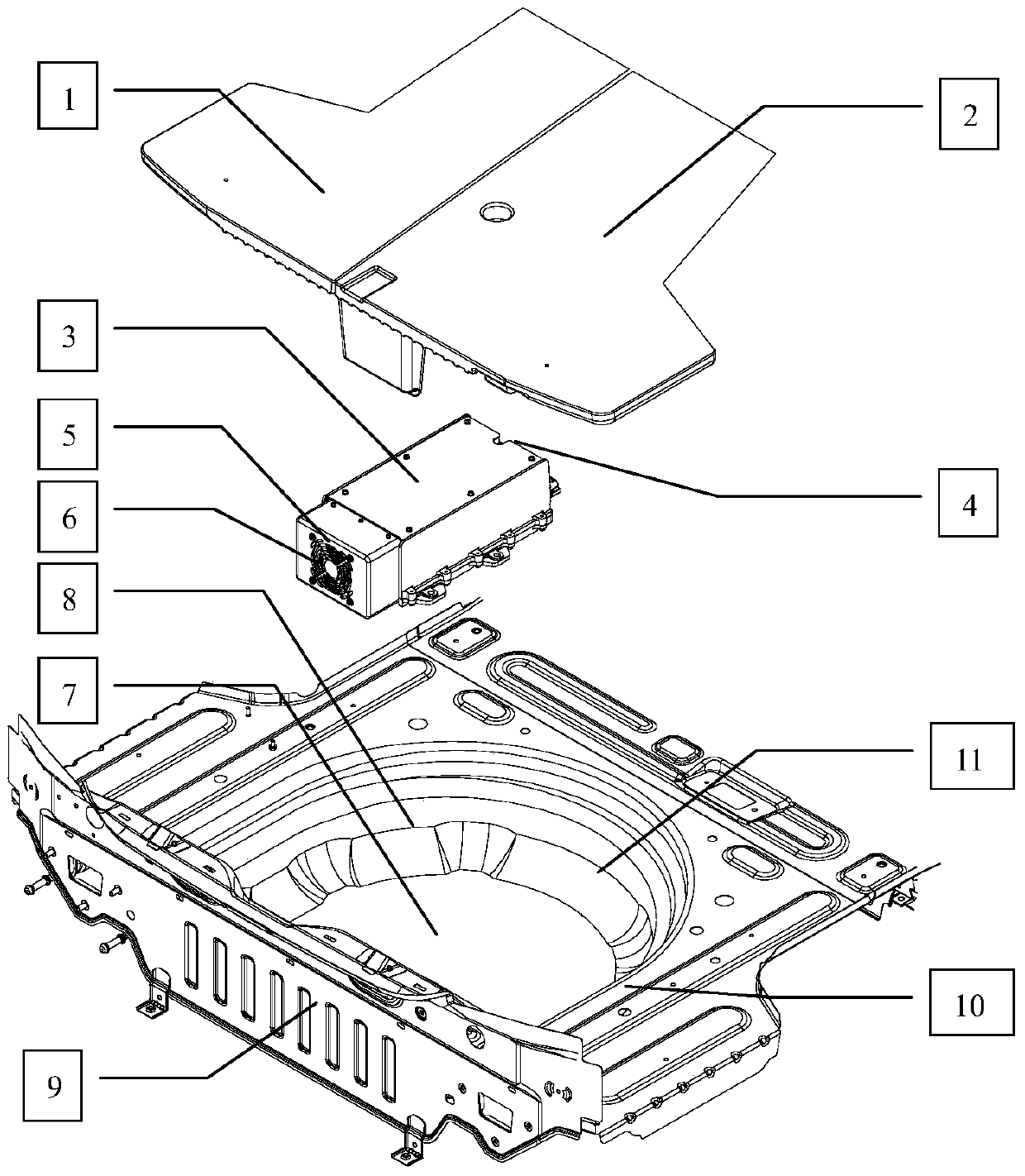
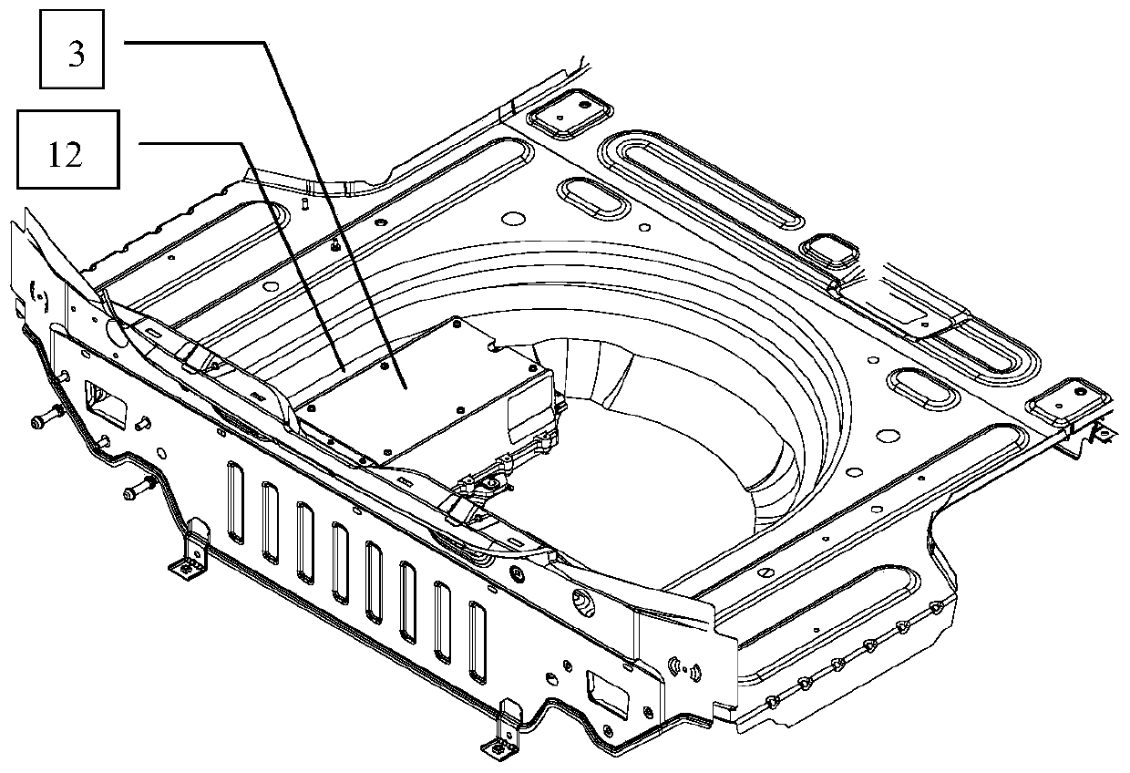
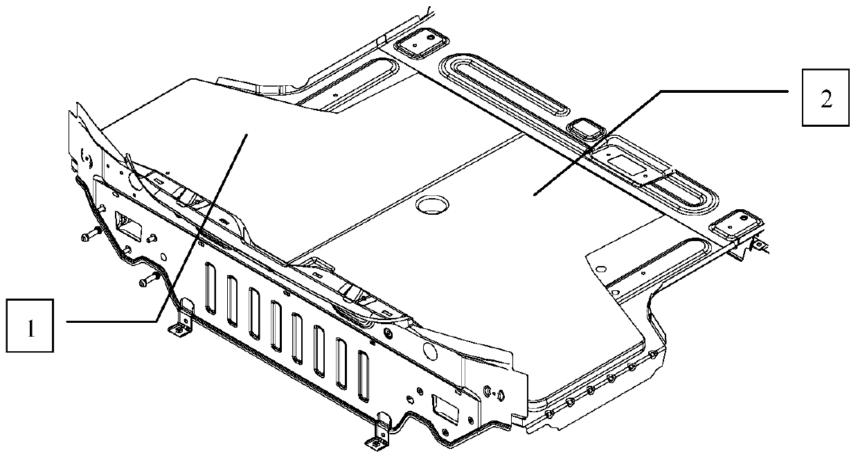
[0038] Foam support block 1, foam support block 2 (such as figure 1 ) is designed according to the sheet metal structure of the on-board charger 3 and the spare tire pool 6, and the EPP material is selected to meet the performance requirements of the vehicle on temperature, structural strength, and durability. Fixed in the spare tire pool 7 (such as figure 2 ), the space between the left side of charger 3 and the side wall 12 between the spare tire well is filled with foam support block 1, and the space between the right side of charger 3 and the right side wall 10 of the spare wheel well is filled with foam support block 1 and foam support block 2 Fill in between, maintain a gap of more than 50mm for air circulation between the air outlet 5 of the car charger and the rear panel 9, and...


PUM


Abstract

The invention relates to an electric-vehicle-mounted charger. The electric-vehicle-mounted charger is fixed into a spare tire pond. The portion between the spare tire pond and the electric-vehicle-mounted charger is filled with supporting parts, gaps are reserved between the supporting parts and the spare tire pond, and cooling loops where air can flow are formed by the gaps between the supporting parts and the spare tire pond. The electric-vehicle-mounted charger is arranged in a closed space of the spare tire pond of a vehicle, an air inlet passage connected with the exterior and an air outlet passage connected with the exterior are avoided, the space occupied by an external air passage is avoided, and meanwhile the development cost is effectively reduced. A cooling fan is integrated in the electric-vehicle-mounted charger, and the space additionally occupied by installing the fan in the external air passage is avoided; internal air cyclically flows along the metal plate wall of the spare tire pond, the aim that overall metal plates of the spare tire pond exchange heat with the exterior to achieve cooling is achieved, and the electric-vehicle-mounted charger is cooled under the sealed condition; and an air passage outlet, opened outwards, of an automobile body is not needed, the development cost is reduced, and water leakage risks caused by hole forming are avoided.

Description

technical field [0001] The invention belongs to the field of electric vehicles, in particular to a cooling arrangement method for an electric vehicle on-board charger. Background technique [0002] As an important part of electric vehicles, on-board chargers are key to layout and cooling. On the premise of meeting the layout and performance requirements of new energy components, how to low cost, high reliability, and small space occupation is the primary problem to be solved. [0003] The current main cooling methods for on-board chargers are natural cooling, forced air cooling and liquid cooling. [0004] The natural cooling solution dissipates heat through natural convection of the air. The structure is simple, but the temperature of the device is high, which has a great impact on the peripheral parts. The car space is generally compact and contrary. [0005] The advantage of the liquid cooling solution is that it requires less layout space and has less impact on periphe...

Claims


Application Information

Patent Timeline
Patent Type & Authority Patents(China)
IPC IPC(8): B60L11/18
CPCY02T10/70
Inventor 郎林曾祥兵
Owner 奇瑞新能源汽车股份有限公司
Why Eureka
Try Eureka