Plate chain type conveyor

A conveyor and plate chain technology, applied in the direction of conveyors, conveyor objects, transportation and packaging, etc., can solve the problems of increased cleaning or disinfection of equipment and materials, increased energy consumption, and easy wear and tear of parts, etc., to achieve reduction The risk of cross-contamination, the effect of less energy consumption and low friction

Active Publication Date: 2015-12-16
GUANGZHOU UNIVERSITY
View PDF6 Cites 15 Cited by
  • Summary
  • Abstract
  • Description
  • Claims
  • Application Information

AI Technical Summary

Problems solved by technology

But this device also has the following disadvantages: 1. Since the conveying blade is actually equivalent to being dragged by the conveying chain to slide on the slide rail, this causes the corresponding parts to be easily worn, and the energy consumption must be increased to overcome the frictional resistance
2. Since one side of the conveying blade is facing up when it is on the upper layer, and the other side is facing up after moving to the lower layer, the material is in contact with the two sides of the conveying blade during the conveying process, which is easy to cause the material to come into contact with the conveying blade. cross-contamination between devices
For example, when transporting sludge, slag, etc., the residues on the transport blades can easily pollute the slide rails, transmission chains, drive sprockets, main shafts and boxes of the equipment; Sprocket contaminants are easily transferred to the food through the conveyor blades
At the same time, the above-mentioned cross-contamination will inevitably lead to an increase in the cleaning or disinfection of equipment and materials in the later stage.

Method used


Image

  • Plate chain type conveyor
  • Plate chain type conveyor
  • Plate chain type conveyor

Examples


Embodiment Construction

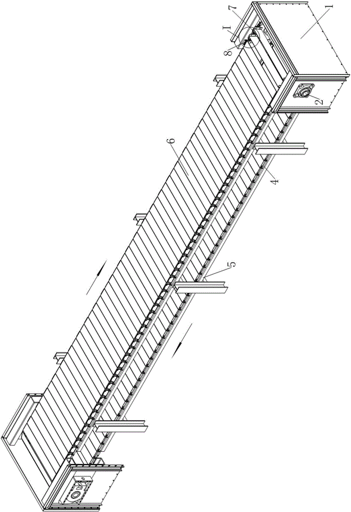
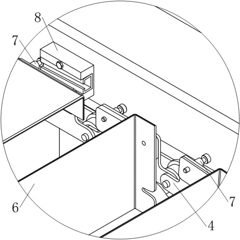
[0021] see Figure 1~2 , in this example, the conveyor includes a frame, two pairs of sprockets 3 and a conveyor belt that is wound around the two pairs of sprockets 3; the frame is composed of the conveyor heads 1 at both ends and the conveyor chain support 5 at the bottom of the conveyor belt; The conveyor belt is composed of two conveyor chains 4 wound in parallel on two pairs of sprockets 3 and a set of material plates 6 straddling the two conveyor chains 4 .

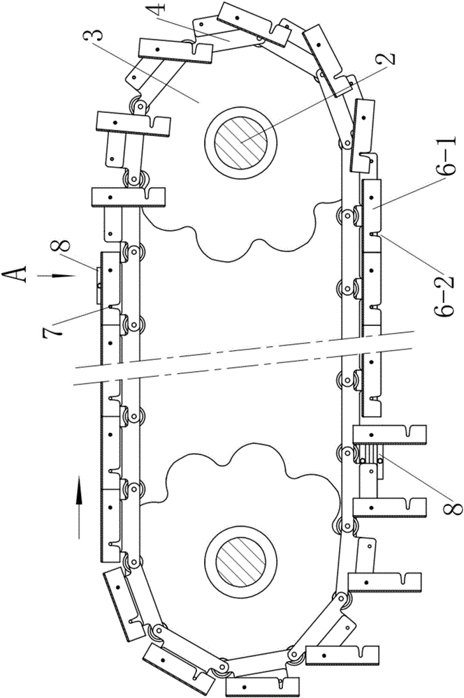
[0022] see figure 1 with 3 , the machine head 1 is spliced ​​by section steel and steel plate, the support shaft 2 is straddled on the box body on both sides of the machine head 1, and two sprockets 3 are fixed on each support shaft 2. The two conveyor chains 4 are respectively wound on the two sprockets 3 on the same side of the two supporting shafts 2 .

[0023] see Figure 3-6 , the conveyor chain 4 is composed of an outer chain plate 4-1, an inner chain plate 4-2 and a roller 4-5, wherein the outer chain pla...


PUM


Abstract

The invention discloses a plate chain type conveyor. The plate chain type conveyor comprises racks, two pairs of chain wheels supported at the two ends of the racks, and conveyor belts which are wound on the two pairs of chain wheels, wherein each conveyor belt is composed of two conveying chains and one group of material plate. The plate chain type conveyor is characterized in that a support lug is arranged at one edge, close to a chain plate on one side of the material plate, of each of the two conveying chains in a manner of extending outwards; a connection hole is formed in one front end of each support lug along the movement direction of the conveying chains, and a spring pin is arranged at the other end of each support lug; the spring pins are fixedly arranged on the outer sides of the support lugs and nail rods of the pins penetrate through the support lugs to enter the inner sides of the support lugs; when the conveying chains are at a stretched state, the distances from each connection hole to the adjacent two spring pins are equal; when the conveyor belts are located on the upper sides of the chain wheels, one end of each material plate is hinged with the connection holes in the support lugs of one pair of chain sections, and the other end of each material plate is supported on one rear spring pin adjacent to the connection holes. Unloading control devices are arranged on the rack close to the rail ends of the upper and lower layers of conveyor belts respectively.

Description

technical field [0001] The present invention relates to a transport device, in particular to a conveyor with endless traction elements, such as chains. Background technique [0002] Plate chain conveyor, also known as chain plate line, is a kind of conveying mechanical equipment that uses a circularly moving chain as a traction element and a metal plate as a conveying carrier. It has wide application range, large conveying capacity, can be used for long-distance conveying and can also carry out various processes such as classification, freezing, drying and assembling during the conveying process, and is widely used in various occasions in industrial production. [0003] However, the traditional plate chain conveyor cannot automatically unload the material to its lower material board, so it can only use the upper material board to convey the material in one direction, and the lower material board is idle and useless. caused a lot of waste. The invention patent application w...

Claims


Application Information

Patent Timeline
Patent Type & Authority Applications(China)
IPC IPC(8): B65G17/06B65G17/30B65G47/34
Inventor 陶建华卢永焰
Owner GUANGZHOU UNIVERSITY
Why Eureka
Try Eureka