Elevator traction machine brake precision control system and method

An elevator traction machine, precision control technology, applied in the direction of the hoisting device, etc., can solve the problems such as the reduction of the effective braking area of ​​the brake shoe, the uneven force on the braking surface, the reduction of the braking force of the brake, etc., and achieves simple structure and low cost. Low, the effect of preventing the drop in braking force

Active Publication Date: 2015-12-16
GUANGZHOU GUANGRI ELEVATOR IND
View PDF6 Cites 2 Cited by
  • Summary
  • Abstract
  • Description
  • Claims
  • Application Information

AI Technical Summary

Problems solved by technology

The braking force at the sintering place will be greatly reduced, which will reduce the effective braking area of ​​the brake shoe, and th

Method used


Image

  • Elevator traction machine brake precision control system and method
  • Elevator traction machine brake precision control system and method
  • Elevator traction machine brake precision control system and method

Examples


Embodiment 1

[0038] The present invention will be further described in detail below in conjunction with the embodiments and the accompanying drawings, but the embodiments of the present invention are not limited thereto.

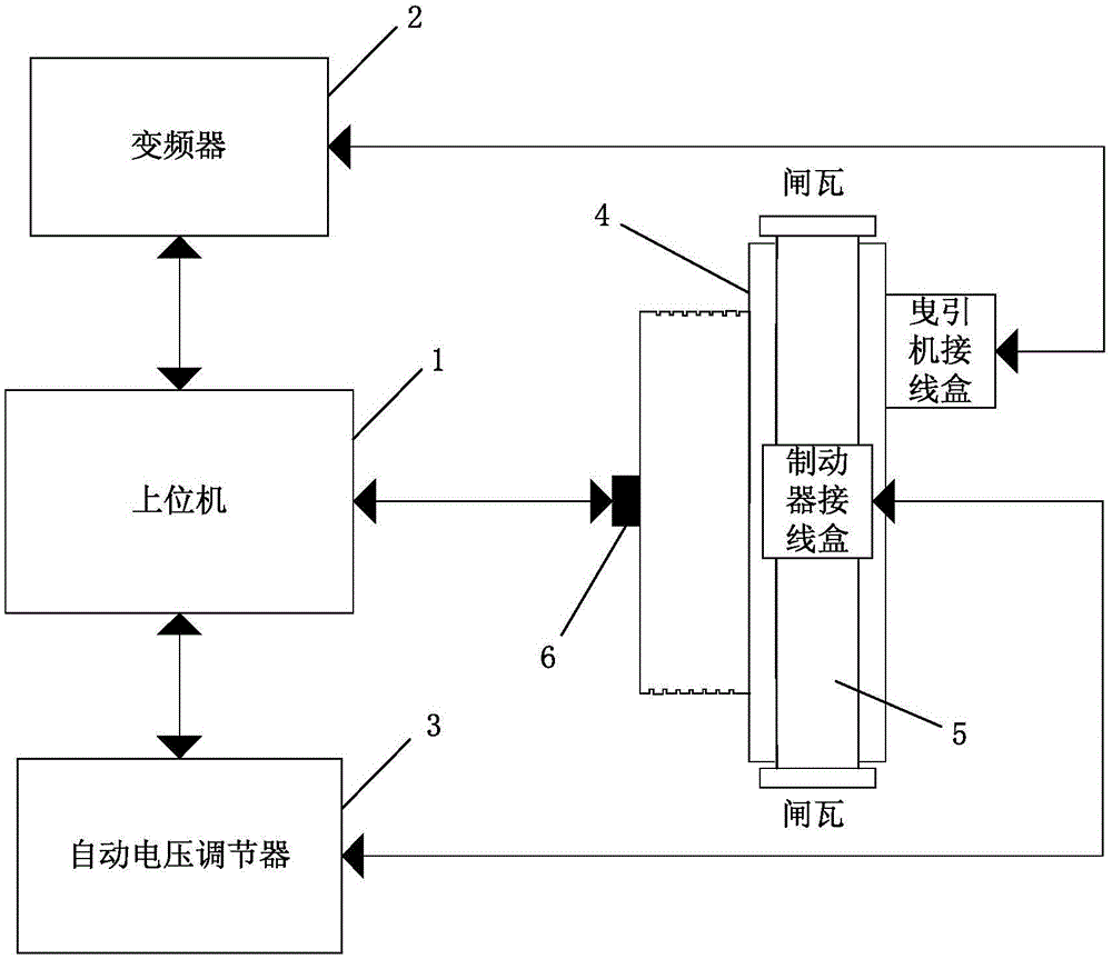
[0039] Such as figure 1 As shown, the system for realizing the precision control of the brake of the elevator traction machine in this embodiment includes a host computer 1, and the host computer 1 is connected with the encoder 6, and is connected with the brake 5 through the automatic voltage regulator 3 (the automatic voltage regulator 3 connected to the junction box of the brake 5), and connected to the traction machine 4 through the frequency converter 2 (the frequency converter 2 is connected to the junction box of the traction machine 4), so as to realize the connection of the frequency converter 2, the automatic voltage regulator 3, Control of the traction machine 4, brake 5 and encoder 6; wherein, the brake is a block brake or a drum brake, the encoder is an incr...

Embodiment 2

[0049] In this embodiment, both the brake and the traction machine are in the state of complete machine installation and commissioning.

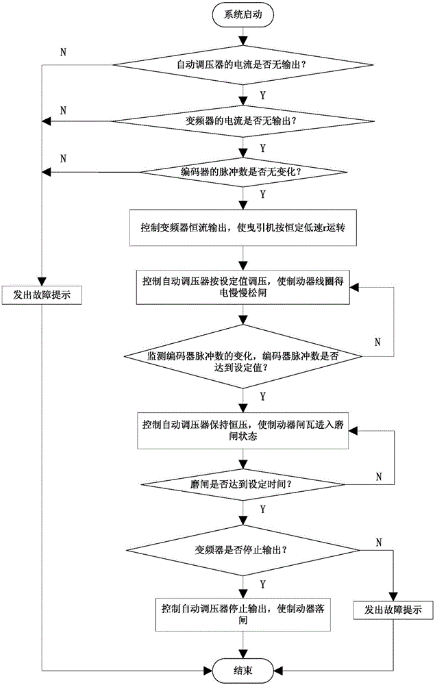
[0050] Such as image 3 As shown, this embodiment provides a method for realizing the precision control of the brake of the elevator traction machine. The method is applied to the host computer and includes the following steps:

[0051] S1. At the initial stage of the system, detect whether the current of the automatic voltage regulator has no output, if so, judge that the brake is in the brake state, and enter step S2, if not, issue a fault prompt, and end the program operation;

[0052] S2. Detect whether the current of the frequency converter has no output. If so, judge that the traction machine is in a non-working state, and proceed to step S3. If not, issue a fault prompt and end this program operation;

[0053] S3. Check whether the number of pulses of the encoder has not changed, if so, enter step S4, if not, issue a fault prompt, and ...


PUM


Abstract

The invention discloses an elevator traction machine brake precision control system and method. The system comprises an upper computer. The upper computer comprises an automatic voltage regulator current state detection module, a frequency converter current state detection module, an encoder pulse number state detection module, an automatic voltage regulator control module, an encoder pulse number monitoring module, a frequency converter output state detection module and an automatic voltage regulator stop control module. A frequency converter, an automatic voltage regulator, a traction machine, a brake and an encoder are controlled by the upper computer. The elevator traction machine brake precision control system and method have the advantages that the cost is low, the reliability is high, operation is convenient, and the structure is simple. The brake control precision is improved on the traction machine achieving complete machine installation directly on the existing production conditions, no other tool equipment needs to be specially designed for carrying out precision machining on the brake, installation and debugging are easy, and the system and method can be widely applied to brake production.

Description

technical field [0001] The invention relates to a system and method for realizing brake precision control, in particular to a system and method for realizing brake precision control of an elevator traction machine, belonging to the field of elevator brake safety. Background technique [0002] In modern society, the elevator has become an indispensable passenger tool in people's life, and its operation safety has attracted more and more attention. The more common car slipping phenomenon in elevator accidents is basically caused by the loss of braking force of the brake. . As an important safety component of the elevator, the service life of the brake directly affects the operation safety of the elevator. [0003] Common brake structures include block type and drum type. Their working principles are based on the contact between the bilateral brake shoes and the brake wheels of the traction machine to generate frictional braking to achieve the effect of stopping the elevator. ...

Claims


Application Information

Patent Timeline
IPC IPC(8): B66D5/30
Inventor 郑志凯周德颀蔡林坊瞿艳陈健豪
Owner GUANGZHOU GUANGRI ELEVATOR IND
Why Eureka
Try Eureka