Assembly type beam column joint and construction method thereof

A beam-column joint and construction method technology, applied in building components, earthquake-proof, construction and other directions, can solve the problems of small lateral stiffness and poor seismic resistance, and achieve the improvement of seismic performance, reduction of residual deformation, and good structural function recovery ability. Effect

Inactive Publication Date: 2015-12-16
SHANDONG JIANZHU UNIV
View PDF9 Cites 15 Cited by
  • Summary
  • Abstract
  • Description
  • Claims
  • Application Information

AI Technical Summary

Problems solved by technology

Reinforced concrete frame structure is a widely used structural form, but its lateral stiffness is small and its earthquake resistance is poor

Method used


Image

  • Assembly type beam column joint and construction method thereof
  • Assembly type beam column joint and construction method thereof
  • Assembly type beam column joint and construction method thereof

Examples


specific Embodiment 1

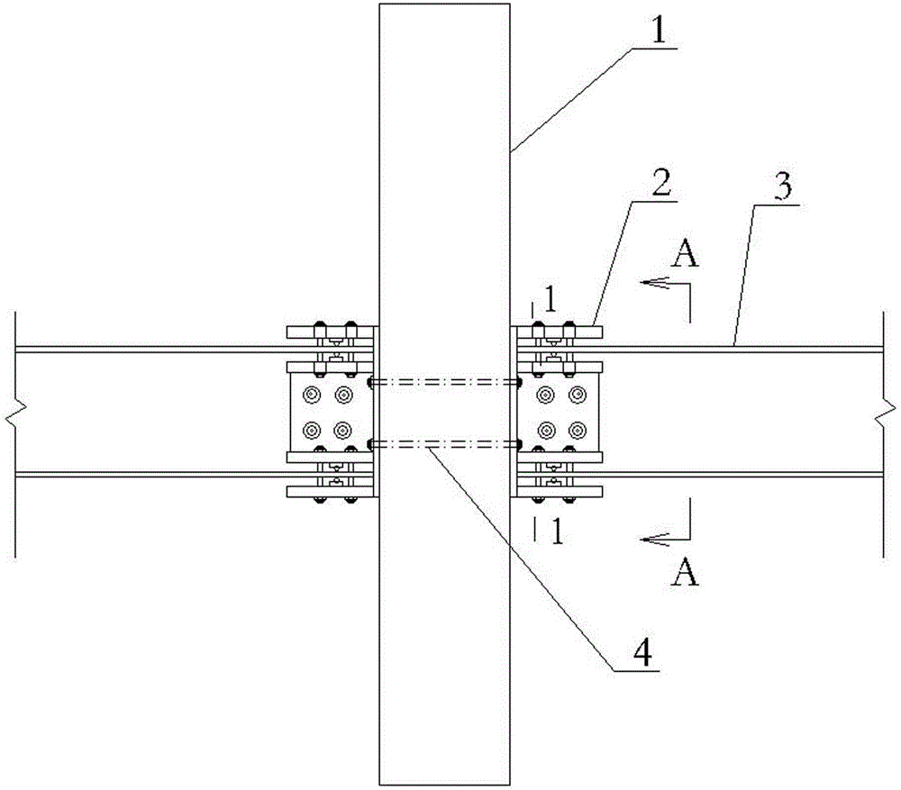
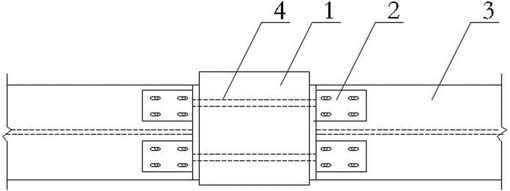
[0027] Such as figure 1 A specific embodiment shown in -4, which includes a concrete column 1, two H-shaped steel beams 3 and two connecting pairs 2. One ends of the two H-shaped steel beams 3 are respectively connected to both sides of the concrete column 1 through a connecting pair 2 .

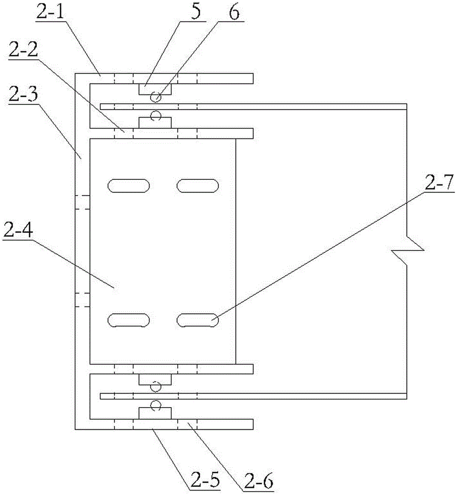
[0028] Such as image 3 As shown in Figure 4, the connection pair 2 includes an end plate 2-3, an upper wing plate 2-1 and a lower wing plate 2-5 respectively fixed on the upper and lower ends of the end plate 2-3, fixed on the end plate 2-3, the upper The web 2-4 between the wing plate 2-1 and the lower wing plate 2-5, the upper wing plate 2-1 includes upper and lower layers, and the upper and lower upper wing plates 2-1 are fixed with the end plate 2-3, Lower wing plate 2-5 comprises upper and lower two layers, and upper and lower lower wing plate 2-5 of two layers is all fixed with end plate 2-3, and the middle part of every layer of upper wing plate 2-1 and every layer of lower wing pl...

specific Embodiment 2

[0033] Such as Figure 7 - Figure 11 As shown, the difference between the second embodiment and the first embodiment is as follows: the connecting pair 2 has no web plate, the end of the H-shaped steel beam 3 far away from the concrete column is provided with a beam end plate 13, and the concrete column 1 is pre-embedded with an isolation pipe 11. The isolating pipe 11 is made of PVC pipe or other materials. The isolating pipe 11 is provided with slidable prestressed tendons 12. The two ends of the prestressed tendons 12 protrude from the concrete column 1 and are respectively fixed on two H-shaped steel bars. On the beam end plate 13 of the beam 3, the prestressed tendon 12 replaces the anchor bolt 4 in the first embodiment.

[0034] The construction method of the present specific embodiment is as follows: the specific embodiment of the present invention comprises the following steps: (1) bind the longitudinal bars and stirrups of the concrete column 1, make the reinforceme...


PUM


Abstract

The invention discloses an assembly type beam column joint and a construction method thereof. An upper flange of a connecting pair is connected with an upper flange of an H-shaped steel beam through bolts; a lower flange of the connecting pair is connected with a lower flange of the H-shaped steel beam through bolts; holes, which are connected with the bolts, of the upper flange and the lower flange of the connecting pair are slot holes of which the length directions are positioned in the length direction of the H-shaped steel beam; and an end plate of the connecting pair is attached to a concrete column. The construction method comprises the following steps of (1) manufacturing the concrete column; (2) manufacturing the H-shaped steel beam and the connecting pair; (3) mounting a particle damping energy-consuming device; (4) connecting the H-shaped steel beam and the connecting pair; and (5) connecting the column and the beam. When an earthquake comes, the bolts can slide in the slot holes, and earthquake energy can be consumed. Even if the joint deforms greatly, attenuation of strength and rigidity and participation deformation are small, residual deformation of the joint can be reduced after the earthquake, and the assembly type beam column joint has good deformation recovery capability and structure function recoverability.

Description

technical field [0001] The invention relates to a beam-column joint in the construction field, and also relates to a construction method for the beam-column joint. Background technique [0002] my country is one of the land-earthquake-prone countries. Especially in recent years, large earthquakes have occurred frequently, and the damage to buildings caused by earthquakes has become more and more serious. Reducing casualties and economic losses caused by structural damage is the source of structural engineering technicians. Responsibilities and obligations. Reinforced concrete frame structure is widely used as a structural form, but its lateral stiffness is small and its seismic performance is poor. [0003] As the assembled integral concrete structure has a high level of industrialization, is convenient for winter construction, reduces the amount of wet work on site, reduces waste of materials, reduces dust and noise on the construction site, so as to achieve the advantages ...

Claims


Application Information

Patent Timeline
Patent Type & Authority Applications(China)
IPC IPC(8): E04B1/58E04B1/98E04G21/14
Inventor 刘春阳王玉镯张华英王灿灿杨大彬杜修力
Owner SHANDONG JIANZHU UNIV
Why Eureka
Try Eureka