A self-cascading refrigeration system with low temperature function
A refrigeration system, self-cascading technology, applied in the direction of refrigerators, refrigeration components, refrigeration and liquefaction, etc., can solve the problems of increasing system complexity, not fully utilizing the cooling capacity of the cold end gas, and detrimental to the refrigeration efficiency of the refrigeration system , to achieve the effect of lowering the refrigeration temperature range, obvious energy saving effect and simple structure
- Summary
- Abstract
- Description
- Claims
- Application Information
AI Technical Summary
Problems solved by technology
Method used
Image
Examples
Embodiment 1
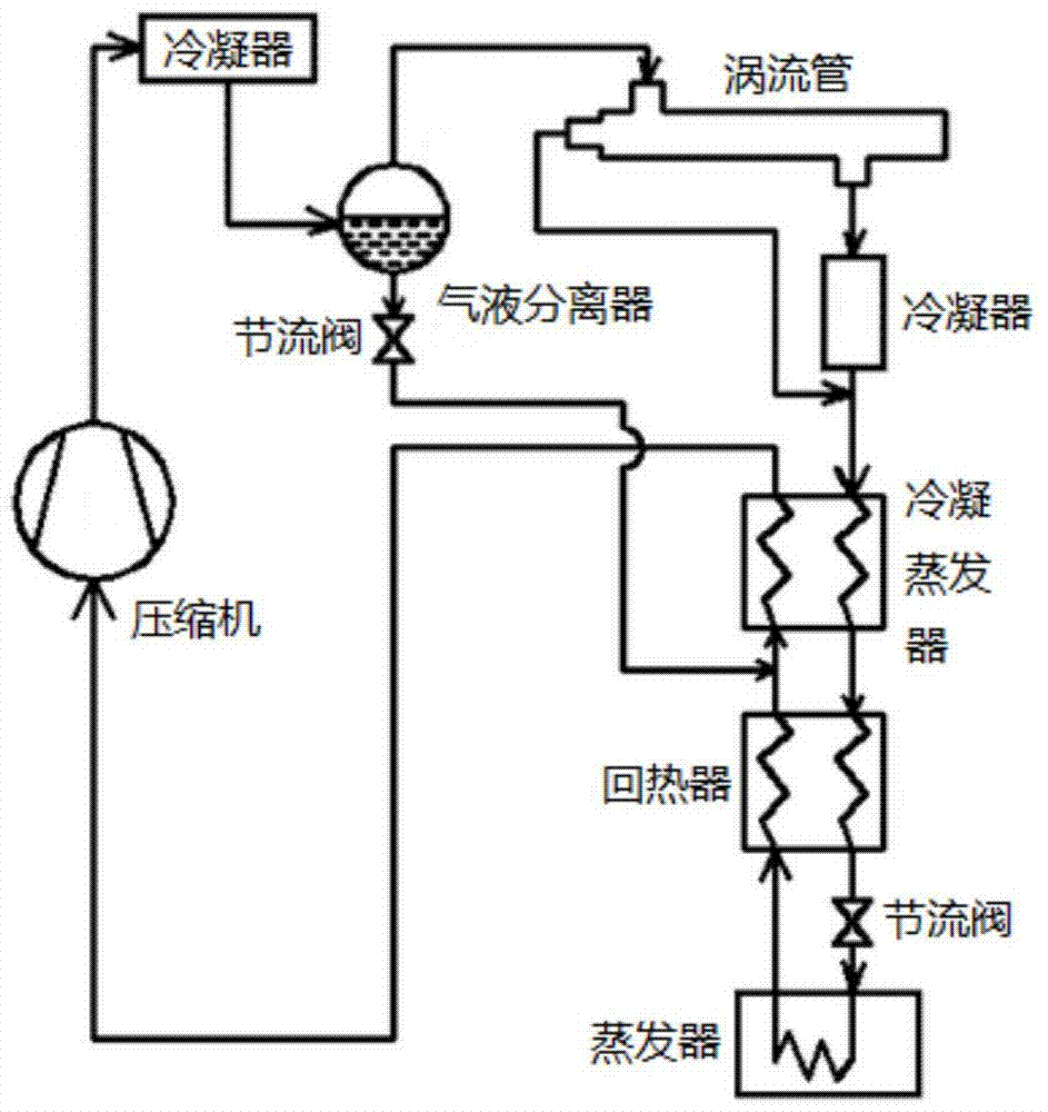
[0036] A self-cascading refrigeration system with low-temperature function provided in this embodiment, such as Figure 4As shown, the system includes a compressor 1, a condenser 2, a vortex tube 3, a gas-liquid separator 4, a condensation evaporator 5, a subcooler 6, a first evaporator 7, a first throttle valve 8, a second section Throttle valve 9 and third throttle valve 10; wherein, the outlet of compressor 1 is connected with condenser 2, the outlet of condenser 2 is connected with gas-liquid separator 4, and the first outlet of gas-liquid separator 4 is connected with the inlet of vortex tube 3 , the gas outlet at the hot end of the vortex tube 3 is connected to the inlet of the second throttle valve 9, the outlet of the second throttle valve 9 is connected to the first inlet of the condensing evaporator 5, the first outlet of the condensing evaporator 5 is connected to the first inlet of the subcooler 6 The first outlet of the subcooler 6 is connected to the inlet of the...
Embodiment 2
[0040] A self-cascading refrigeration system with low-temperature function provided in this embodiment, such as Figure 5 As shown, the system includes a compressor 1, a condenser 2, a vortex tube 3, a gas-liquid separator 4, a condensation evaporator 5, a subcooler 6, a first evaporator 7, a first throttle valve 8, a second section Flow valve 9, third throttle valve 10 and second evaporator 11; wherein, the outlet of compressor 1 is connected with condenser 2, the outlet of condenser 2 is connected with gas-liquid separator 4, and the first outlet of gas-liquid separator 4 It is connected with the inlet of the vortex tube 3, the gas outlet of the hot end of the vortex tube 3 is connected with the inlet of the second throttle valve 9, the outlet of the second throttle valve 9 is connected with the first inlet of the condensing evaporator 5, the first outlet of the condensing evaporator 5 is connected with the The first inlet of the cooler 6 is connected, the first outlet of th...
PUM
 Abstract
Description
Claims
Application Information
 - R&D Engineer
- R&D Manager
- IP Professional
- Industry Leading Data Capabilities
- Powerful AI technology
- Patent DNA Extraction
Browse by: Latest US Patents, China's latest patents, Technical Efficacy Thesaurus, Application Domain, Technology Topic, Popular Technical Reports.
© 2024 PatSnap. All rights reserved.Legal|Privacy policy|Modern Slavery Act Transparency Statement|Sitemap|About US| Contact US: help@patsnap.com


