Test device and measurement method for fatigue crack growth rate in seawater corrosive environment

A technology for fatigue crack growth and rate testing, applied in the field of fatigue crack growth rate testing devices under seawater corrosion environment, can solve the problems of heat generation, influence the validity of test results, and strict sealing performance requirements, and achieve the effect of strong practicability

Active Publication Date: 2018-04-17
武汉钢铁有限公司
View PDF8 Cites 0 Cited by
  • Summary
  • Abstract
  • Description
  • Claims
  • Application Information

AI Technical Summary

Problems solved by technology

Invention patent CN202119748U "a test device for corrosion fatigue crack growth" designed a corrosion medium box suitable for the central crack M (T) sample, the box is stuck on the test section of the sample when the fatigue test and There is friction between the samples, and the sealing performance requirements are very strict. Once leaked, the corrosive medium will corrode the fatigue test equipment. In addition, the resistance sheet is used to test the crack growth. It needs to be calibrated before each test. It is better to use the COD gauge and use the flexibility method directly. Easy to measure
Invention patent application CN101358929A "An environmental device for fatigue crack growth rate test in a corrosive environment" also developed an environmental box stuck in the crack growth area on the surface of the sample. space, to prevent the COD gauge from being corroded by the corrosive medium, but this device is only suitable for compact tensile C(T) samples, and due to the small volume of the medium box, a small amount of corrosive medium may move up and down with the sample at high frequency in a small space. Heating causes changes in the stress field at the crack tip and affects the validity of the test results

Method used


Image

  • Test device and measurement method for fatigue crack growth rate in seawater corrosive environment
  • Test device and measurement method for fatigue crack growth rate in seawater corrosive environment
  • Test device and measurement method for fatigue crack growth rate in seawater corrosive environment

Examples


Embodiment Construction

[0036] Below in conjunction with accompanying drawing and specific embodiment the present invention is described in further detail:

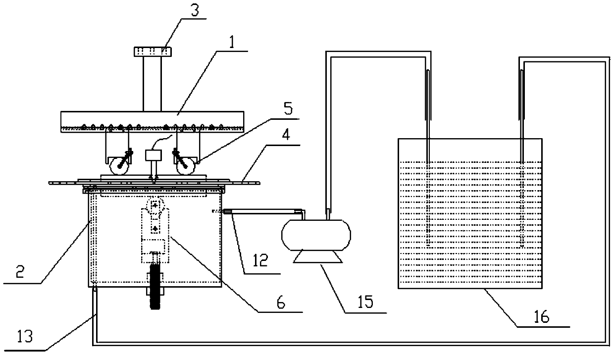
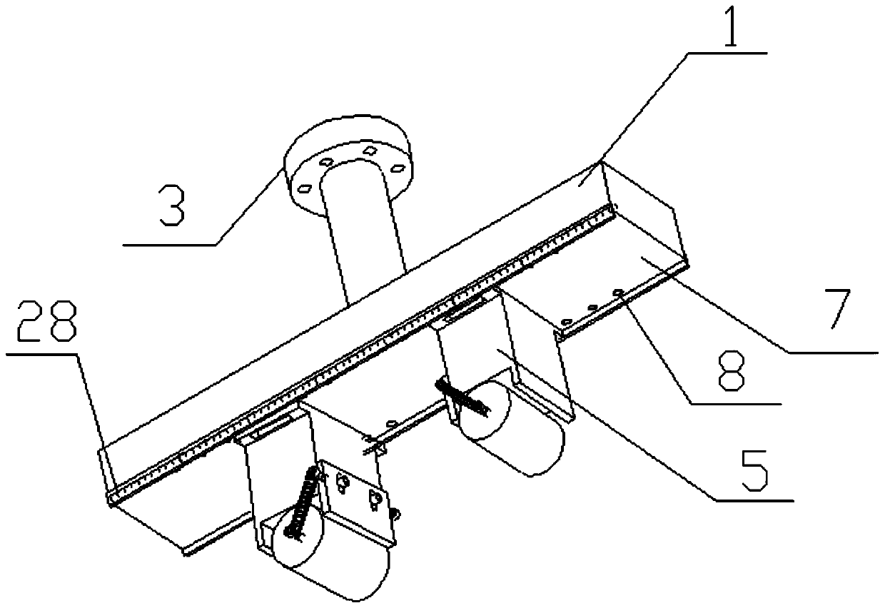
[0037] Such as figure 1 The shown inventive device for fatigue crack growth rate test under seawater corrosion environment includes a three-point bending fixture and a seawater environment container box 2 . The three-point bending fixture is composed of a three-point bending support 1 connected to the crossbeam of the fatigue testing machine, two upper bending center fixtures 5 connected on the three-point bending support 1, and a lower bending center arranged in the seawater environment container box 2 The fixture consists of 6 components. The seawater environment container box 2 is connected with a circulating seawater supply device located outside the seawater environment container box. The circulating seawater supply device includes a circulating seawater tank 16 and a circulating water pump 15. The bottom of the seawater environment conta...


PUM


Abstract

The invention provides a fatigue crack growth rate test device and its measurement method in seawater corrosion environment, which is characterized in that it includes a three-point bending fixture, the seawater environment container box and the seawater environment container box located outside the seawater environment container box The circulating seawater supply device is connected. The invention is applicable to the measurement of the fatigue crack growth rate of the unilateral notch SE(B) sample, and the conventional three-point bending fixture is inverted to ensure that the mechanically processed notch of the SE(B) sample and the flexibility measurement COD gauge are placed at the sea level Above, the crack extension can be measured by the flexibility method and the COD gauge will not be corroded when it is placed in seawater. In addition, the anti-splash cover prevents seawater from splashing during the fatigue test, corrodes the fixture system and the fatigue testing machine, and has strong practicability.

Description

technical field [0001] The invention belongs to the technical field of testing the mechanical properties of metal materials, and specifically refers to a fatigue crack growth rate testing device and a measuring method thereof in a seawater corrosion environment. Background technique [0002] The fatigue crack growth rate test is an important test to evaluate the fatigue performance of metal materials. In the seawater corrosion environment, the fatigue crack growth of the material will be accelerated, so the investigation of the fatigue crack growth rate of the material in the corrosion environment is more pertinent for the corrosion-resistant steel varieties. [0003] The national standard GB / T6398-2000 "Metallic Materials Fatigue Crack Growth Rate Test Method" appendix C introduces the test device under aqueous medium, but it is limited to the center crack M(T) specimen and the compact tension C(T) For the sample, there is no suitable test device for the unilateral notch S...

Claims


Application Information

Patent Timeline
Patent Type & Authority Patents(China)
IPC IPC(8): G01N3/32
Inventor 刘冬薛欢杜丽影陈士华宋育来吴立新余立彭文杰
Owner 武汉钢铁有限公司
Why Eureka
Try Eureka