
Novel fiber vibration acceleration sensor with simple structure

An acceleration sensor and optical fiber vibration technology, applied in the direction of acceleration measurement, instruments, and measuring devices using inertial force, can solve the problems of susceptibility to temperature, complex structure and high price of vibration sensors and demodulation systems, and achieve flexible production , high promotion and application value, and the effect of improving accuracy

Inactive Publication Date: 2015-12-16
NORTH CHINA ELECTRIC POWER UNIV (BAODING)
View PDF7 Cites 9 Cited by
  • Summary
  • Abstract
  • Description
  • Claims
  • Application Information

AI Technical Summary

Problems solved by technology

[0005] The object of the present invention is to provide a kind of optical fiber vibration acceleration sensor that is used for measuring mechanical vibration acceleration, realize the measurement of mechanical vibration acceleration by measuring the change of the optical power reflected by the end of the optical fiber, solve the existing vibration sensor and demodulation system complex structure, expensive High, easily affected by temperature and other issues

Method used


Image

  • Novel fiber vibration acceleration sensor with simple structure
  • Novel fiber vibration acceleration sensor with simple structure
  • Novel fiber vibration acceleration sensor with simple structure

Examples


Embodiment Construction

[0030] The optical fiber vibration acceleration sensor of the present invention will be described in detail below with reference to the drawings and embodiments.

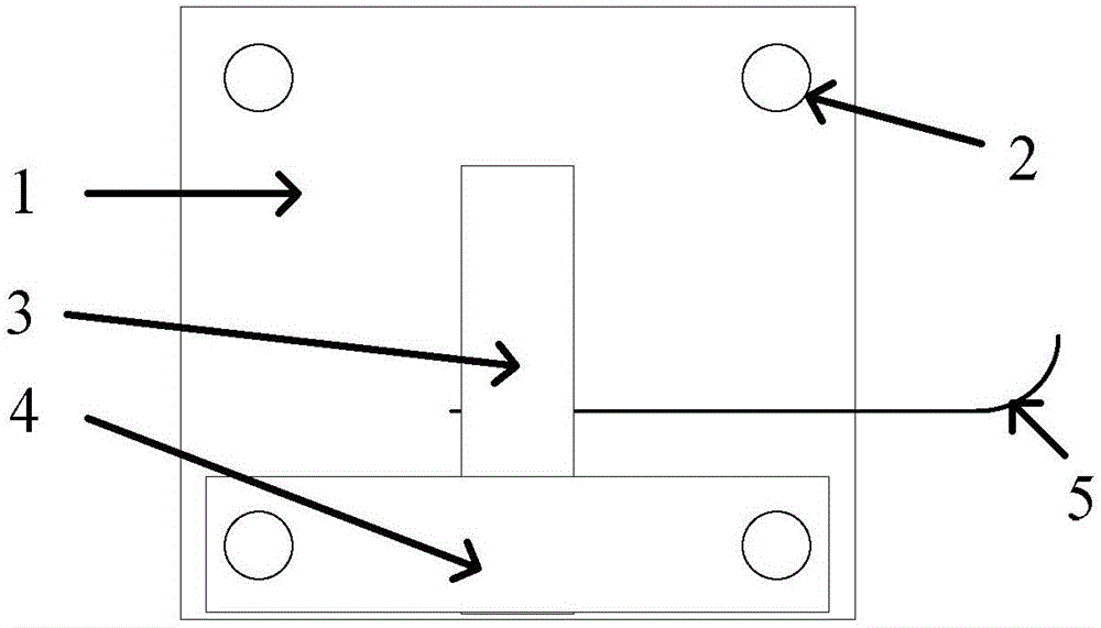
[0031] figure 1 The specific structure of the optical fiber vibration acceleration sensor of the present invention is provided. The optical fiber vibration acceleration sensor provided by the present invention consists of a substrate 1, a cantilever beam 3, a fixed piece 4, and a single-mode fiber fixed between the cantilever beam 3 and the substrate 1. The optical fiber 5 is composed of; the cantilever beam 3 is installed and fixed on the substrate 1, and four positioning holes 2 are respectively provided on the four corners of the substrate 1, which are used to fix the substrate 1 on the object to be measured, two of which are used for Install the fixing piece 4.

[0032] Optical fiber vibration acceleration sensor comprises substrate 1, and the embodiment of substrate 1 is a square, and its side length is 50mm, ...


PUM


Abstract

Disclosed in the invention is a novel fiber vibration acceleration sensor with a simple structure. The sensor comprises a substrate, a cantilever beam, a fixed plate, and a single-mode fiber. Fixed holes are respectively formed in positions, with identical dimensions, of the four corners of the substrate. The cantilever beam is installed on the substrate and approaches the sideline of the substrate; and on end of the cantilever beam is fixed and the other end is suspended. The middle part of the fixed plate exert pressing forces to fix one end of the cantilever beam. The single-mode fiber is fixed between the substrate and the cantilever beam in a pressed mode. When a vibration signal is applied to the cantilever beam, the cantilever beam extrudes the sensing fiber and thus slight deformation of the fiber is caused, so that a reflected optical power generated at the tail end of the fiber is modulated by the vibration signal; and a photoelectric detector detects the change of the optical power to determine the frequency and amplitude of the vibration signal. With the sensor, problems of complicated structure and high cost and poor stability due to the complicated structures of the existing fiber vibration acceleration sensor and the demodulation system thereof can be solved.

Description

technical field [0001] The invention relates to the field of vibration acceleration sensing, in particular to a novel optical fiber vibration acceleration sensor with simple structure. Background technique [0002] Compared with traditional vibration acceleration sensors based on piezoelectric structures, vibration acceleration sensors based on optical fiber structures have the characteristics of anti-electromagnetic interference, high sensitivity, and easy reuse, and have been widely used in civil engineering, aerospace, petrochemical and other fields. . Measuring vibration acceleration is a commonly used method for vibration monitoring. According to different sensing principles, currently widely studied fiber optic vibration acceleration sensors can be divided into wavelength modulation type, phase modulation type, polarization modulation type, and intensity modulation type. Wavelength modulation sensors use fiber gratings as sensitive devices, phase modulation sensors us...

Claims


Application Information

Patent Timeline
Patent Type & Authority Applications(China)
IPC IPC(8): G01P15/03G01H9/00
Inventor 姚国珍李永倩杨志尚秋峰
Owner NORTH CHINA ELECTRIC POWER UNIV (BAODING)
Learn More