Compact microwave topology beam splitter
A beam splitter and compact technology, applied in the field of compact microwave topology beam splitters, can solve the problems of insufficient compact structure, crosstalk, unfavorable integration, etc., and achieve the effect of high-efficiency transmission and anti-crosstalk transmission
- Summary
- Abstract
- Description
- Claims
- Application Information
AI Technical Summary
Problems solved by technology
Method used
Image
Examples
Embodiment 1
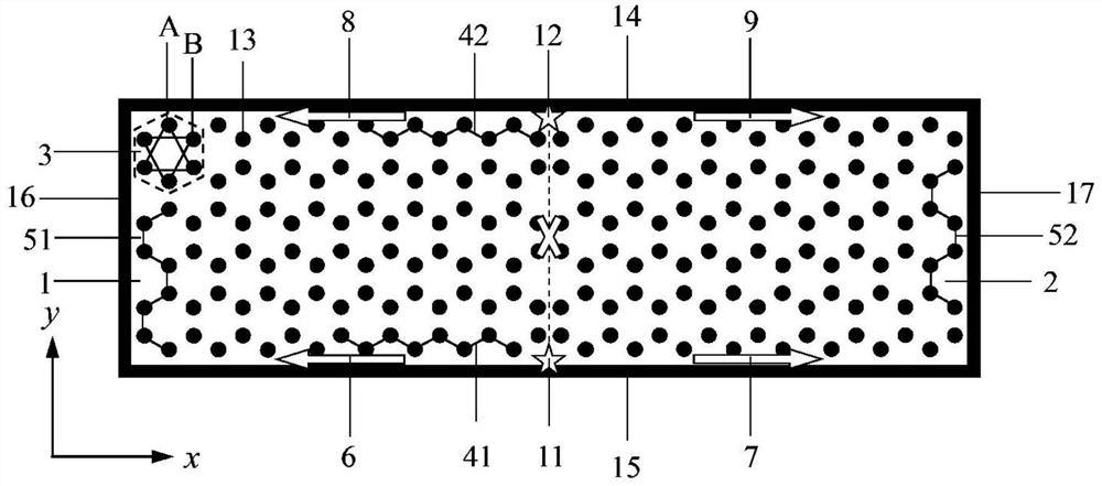
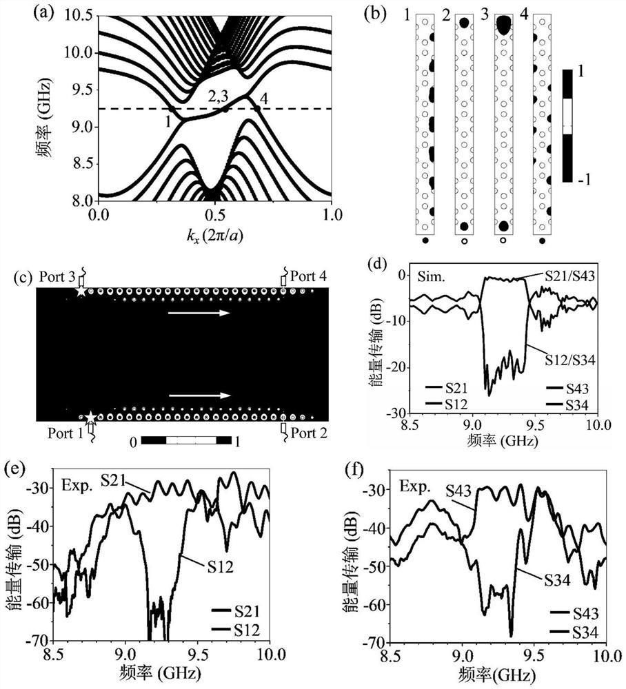
[0071] Figure 4 Figure a is a structural diagram of an embodiment of the compact microwave topological beam splitter of the present invention, and its structural principle is the same as figure 1 structure is consistent. Each rectangular honeycomb antichiral magneto-optic photonic crystal is 25a long and 8 honeycomb lattices 3 wide. The distance between the first antichiral magneto-optic crystal 1 and the second antichiral magneto-optic crystal 2 and the splicing line is 0.3a. The lattice constant a of the honeycomb lattice 3 is 10mm, and the radius of the dielectric column 12 is 0.15a. The excitation frequency range of the first point light source 11 and the second point light source 12 is 9.1-9.4 GHz. Figure 4 Figures b, c, d and e of the Figure 4 Figure a corresponds to the experimental transmission spectra of the first channel 6, the second channel 7, the third channel 8 and the fourth channel 9. Due to the inevitable operational error caused by the experimental mea...
Embodiment 2
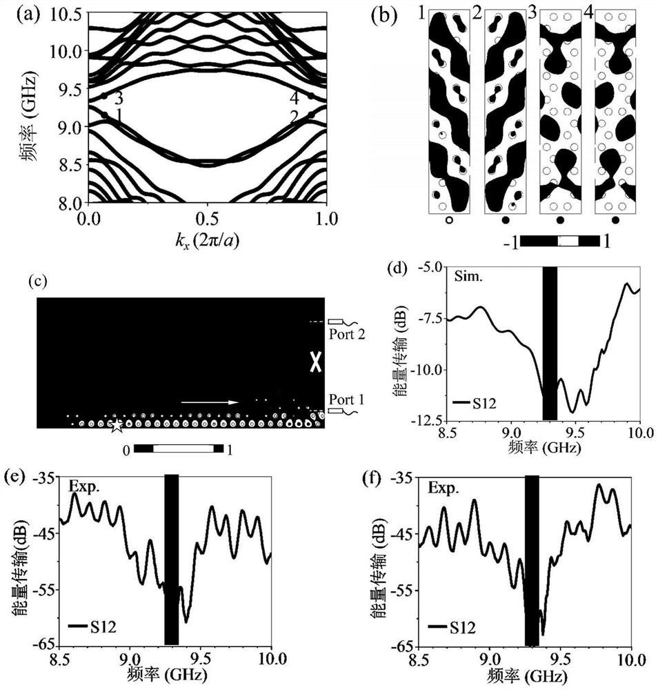
[0074] Figure 6 It is an embodiment of a compact microwave topological beam splitter of the present invention with controllable splitting ratio. Except that the source conditions are different, all the other features are the same as in Example 1. Figure 6 The electric field intensities of the first channel 6 and the second channel 7 are calculated and displayed, so that the light splitting ratio of the first channel 6 and the second channel 7 can be clearly obtained. Figure 6 In the figure a, the electromagnetic wave is incident on the lower zigzag boundary 41 from the -x direction at an angle of 30°, and the waveguide with the splitting ratio of the first channel 6 and the second channel 7 at the lower zigzag boundary 41 is 1:5 through linear scanning calculation , Figure 6 In Figure b, when the electromagnetic wave is incident on the lower zigzag boundary 41 from the -x direction at an angle of 60°, a waveguide with a splitting ratio of the first channel 6 and the seco...
Embodiment 3
[0076] Figure 7 A schematic structural diagram of an embodiment of a compact microwave topological beam splitter of the present invention that realizes two-way four-channel and controllable splitting ratio of each channel, which is the source of changing the upper zigzag boundary 42 on the basis of embodiment 2 The excitation conditions control the light splitting ratio of the third channel 8 and the fourth channel 9, and the rest of the features are the same as those in Embodiment 2. On the upper zigzag boundary 42 electromagnetic waves are incident from the +x direction at an angle of 30°, and the light splitting ratio of the third channel 8 and the fourth channel 9 on the upper zigzag boundary 42 is 5:3; while at the lower zigzag boundary 41 electromagnetic waves are incident at 30° The angle is incident from the -x direction, and the lower zigzag boundary 41 is obtained, and the light splitting ratio of the first channel 6 and the second channel 7 is 3:5. Through this em...
PUM
 Abstract
Description
Claims
Application Information
 - R&D
- Intellectual Property
- Life Sciences
- Materials
- Tech Scout
- Unparalleled Data Quality
- Higher Quality Content
- 60% Fewer Hallucinations
Browse by: Latest US Patents, China's latest patents, Technical Efficacy Thesaurus, Application Domain, Technology Topic, Popular Technical Reports.
© 2025 PatSnap. All rights reserved.Legal|Privacy policy|Modern Slavery Act Transparency Statement|Sitemap|About US| Contact US: help@patsnap.com


