Optical echo wall micro-cavity structure etched by focused ion beam and method for etching same with focused ion beam

A technology of focusing ion beams and whispering galleries, applied in the coupling of optical waveguides, etc., can solve the problems of complex microsphere filling process, and achieve the effect of lower threshold and high sensing sensitivity

Active Publication Date: 2015-12-16
CHONGQING UNIV
View PDF3 Cites 3 Cited by
  • Summary
  • Abstract
  • Description
  • Claims
  • Application Information

AI Technical Summary

Problems solved by technology

[0004] The research on the integration of optical whispering gallery and microcavity is an inevitable requirement for its practical application. The integration can be realized by filling microspheres of various materials in structures such as microfibers or corroded photonic crystal fibers and corroded ultra-thin-walled capillaries. Optical whispering gallery microcavity, but the microsphere filling process is very complicated and is selective to the material (mainly including refractive index and transparent bandwidth) and size of the microsphere. It is the current optical Important problems faced in the field of whispering gallery microcavity

Method used


Image

  • Optical echo wall micro-cavity structure etched by focused ion beam and method for etching same with focused ion beam
  • Optical echo wall micro-cavity structure etched by focused ion beam and method for etching same with focused ion beam

Examples


Embodiment Construction

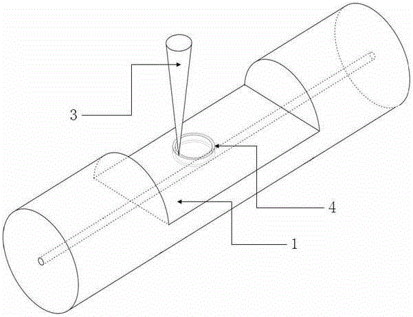
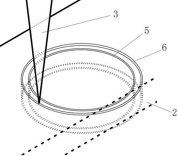
[0021] An optical whispering gallery microcavity structure processed by focused ion beam etching, including an optical fiber 1, the innovation of which is: a plane is arranged on the circumferential side wall of the optical fiber 1, the plane is parallel to the axis of the optical fiber 1, and the plane is parallel to the axis of the optical fiber 1. There is a distance between the cores of the optical fiber 1; two annular grooves are arranged on the plane, the axial direction of the annular groove is perpendicular to the plane, the two annular grooves have the same center, and the axial depths of the two annular grooves are the same; The solid part between the two annular grooves forms an annular protrusion, the radial width of the annular protrusion is smaller than the diameter of the fiber core; the annular protrusion intersects the fiber core; the fiber core is in the axial direction of the annular protrusion The location is within the axial span range of the annular protru...


PUM


Abstract

Provided is an optical echo wall micro-cavity structure etched by a focused ion beam. The optical echo wall micro-cavity structure comprises a fiber. A plane is disposed on the circumferential sidewall of the fiber and is provided with two concentric annular grooves. The two annular grooves have same axial depth. A solid part between the two annular grooves forms an annual protrusion. The annual protrusion has a radial width less than the diameter of a fiber core and intersects with the fiber core. The position, in the axial direction of the annual protrusion, of the fiber core is located within the axial spanning range of the annual protrusion. The annual protrusion forms the optical echo wall micro-cavity structure. The optical echo wall micro-cavity structure has beneficial effects of being high in sensing sensitivity and being decreased in a threshold value of a nonlinear optical phenomenon in an echo wall resonant cavity.

Description

technical field [0001] The invention relates to a fiber-type optical whispering gallery microcavity structure, in particular to an optical whispering gallery microcavity structure and method processed by focused ion beam etching. Background technique [0002] The optical whispering gallery microcavity confines light in the resonant cavity through continuous total reflection at the boundary of the dielectric cavity, so it has the characteristics of ultra-high quality factor and ultra-small mode volume. Mechanics and ultra-low threshold lasers have important application prospects. [0003] At present, microcavities that can form optical whispering gallery modes include structures such as microspheres, microdisks, and microrings; these resonant cavity structures are generally fabricated by mechanical grinding, surface tension, and femtosecond laser pulses; among them, mechanical grinding is used to produce Due to the limitations of the technical conditions of the mechanical gr...

Claims


Application Information

Patent Timeline
IPC IPC(8): G02B6/24
CPCG02B6/24
Inventor 朱涛史磊磊
Owner CHONGQING UNIV
Why Eureka
Try Eureka