Optimization design method for uniform liquid distribution of heat exchanger

An optimized design and heat exchanger technology, which is applied in the direction of instruments, calculations, and special data processing applications, can solve the problems of long experiment time, many manpower and material resources, and large loss, so as to save manpower and material resources, facilitate model modification, and shorten the calculation cycle. short effect

Active Publication Date: 2015-12-16
广东西屋康达空调有限公司
View PDF3 Cites 6 Cited by
  • Summary
  • Abstract
  • Description
  • Claims
  • Application Information

AI Technical Summary

Problems solved by technology

Such a liquid separation capillary design method has the following disadvantages: (1) It is necessary to manufacture a physical model and continuously modify the size of the liquid separation capillary, which consumes a lot of manpower and material resources, and the loss is large; 2) The experiment time is long and the method is complicated. When there are many heat exchange tubes in the heat exchanger, the required workload will be huge and cumbersome, and the traditional method is difficult to achieve

Method used


Image

  • Optimization design method for uniform liquid distribution of heat exchanger
  • Optimization design method for uniform liquid distribution of heat exchanger
  • Optimization design method for uniform liquid distribution of heat exchanger

Examples


Embodiment Construction

[0027] The preferred embodiments of the present invention will be described below in conjunction with the accompanying drawings. It should be understood that the preferred embodiments described here are only used to illustrate and explain the present invention, and are not intended to limit the present invention.

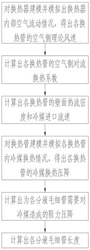
[0028] The optimal design method for uniform liquid separation of the heat exchanger mainly calculates the required size of each liquid separation capillary 3 by calculating how much resistance and pressure drop each liquid separation capillary 3 needs to cause to the refrigerant in order to achieve a reasonable liquid separation. relationship, as follows:

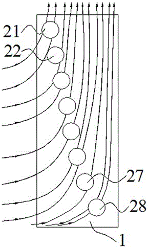
[0029] Step A: Modeling the heat exchanger 1 and simulating its internal air flow to obtain the theoretical wind speed on the air side of each heat exchange tube 21-28

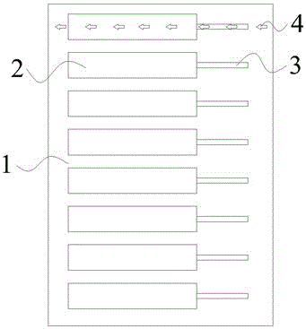
[0030] The model sketch of heat exchanger 1 in the present embodiment is as follows figure 2 As shown, the heat exchanger 1 is provided with ...


PUM


Abstract

The invention discloses an optimization design method for uniform liquid distribution of a heat exchanger. The method comprises: simulating an air flow state in the heat exchanger and a refrigerant heat exchange state of each heat exchange pipe by using FLUENT software, obtaining the refrigerant heat exchange state of each heat exchange pipe, and obtaining a refrigerant heat exchange pressure drop of each heat exchange pipe according to the refrigerant heat exchange state of each heat exchange pipe; and according to the refrigerant heat exchange pressure drop of each heat exchange pipe, assuming that a resistance pressure drop required to be applied to a refrigerant by each liquid distribution capillary tube is reversely deduced when the refrigerant is reasonably utilized, and finally obtaining the required size of each liquid distribution capillary tube, wherein an obtained result is accurate. The method has the following advantages: (1) a working state of the heat exchanger is simulated by constructing a virtual model, so that the calculation cycle is short and the manpower and material resources are saved; and (2) the result can be obtained through computer operation, the operation is simple and convenient, the model is convenient to modify, and a complicated model can be adapted.

Description

technical field [0001] The invention belongs to the field of design methods of air-conditioning components, in particular to an optimal design method for uniform liquid separation of heat exchangers. Background technique [0002] The heat exchanger is an important part of the air conditioning system. It exchanges heat by sending the refrigerant to different heat exchange tubes in the heat exchanger. In actual use, due to the influence of factors such as uneven wind field and height difference, the areas corresponding to different heat exchange tubes in the heat exchanger will have different heat transfer amounts, so it is necessary to adjust the heat transfer to each heat exchange tube The amount of refrigerant is adapted to the heat exchange capacity of each heat exchange tube, thereby improving the utilization rate of refrigerant. In order to achieve reasonable liquid separation, people usually use a liquid separation device to divert the refrigerant at different flow rat...

Claims


Application Information

Patent Timeline
Patent Type & Authority Applications(China)
IPC IPC(8): G06F17/50
Inventor 蔡湛文彭景华严俊杰
Owner 广东西屋康达空调有限公司
Why Eureka
Try Eureka