A cleaning liquid collection device

A liquid collection, gas-liquid collection technology, applied in semiconductor/solid-state device manufacturing, electrical components, circuits, etc., can solve problems such as increased production costs, waste of liquid medicine, rebound, etc., to save production costs and improve recycling efficiency , the effect of preventing cross-contamination

Active Publication Date: 2018-02-23
BEIJING SEVENSTAR ELECTRONICS CO LTD
View PDF5 Cites 0 Cited by
  • Summary
  • Abstract
  • Description
  • Claims
  • Application Information

AI Technical Summary

Problems solved by technology

In this process, due to the high kinetic energy of the liquid particles thrown out at high speed, when they hit the side wall of the liquid collection structure, they may rebound, causing chemical reagents and cleaning products to splash back to the edge of the wafer. even the backside of the wafer, causing contamination
If this pollution cannot be removed in time, it will cause defects on the edge and back of the wafer, especially in the subsequent high-temperature processing process, which will cause the contamination on the edge and back of the wafer to spread to the front, seriously affecting the quality of the wafer
On the other hand, the splash back of the liquid cleaning medium will also cause waste of liquid medicine and increase production costs
[0004] In the existing technology, there is currently no method that can effectively prevent the liquid cleaning medium from splashing back, so that the quality of the wafer cannot be further improved

Method used


Image

  • A cleaning liquid collection device
  • A cleaning liquid collection device
  • A cleaning liquid collection device

Examples


Embodiment Construction

[0030] The specific embodiment of the present invention will be further described in detail below in conjunction with the accompanying drawings.

[0031] It should be noted that, in the following specific embodiments, when describing the embodiments of the present invention in detail, in order to clearly show the structure of the present invention for the convenience of description, the structures in the drawings are not drawn according to the general scale, and are drawn Partial magnification, deformation and simplification are included, therefore, it should be avoided to be interpreted as a limitation of the present invention.

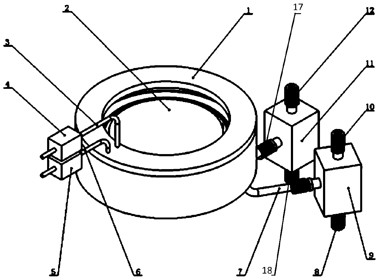
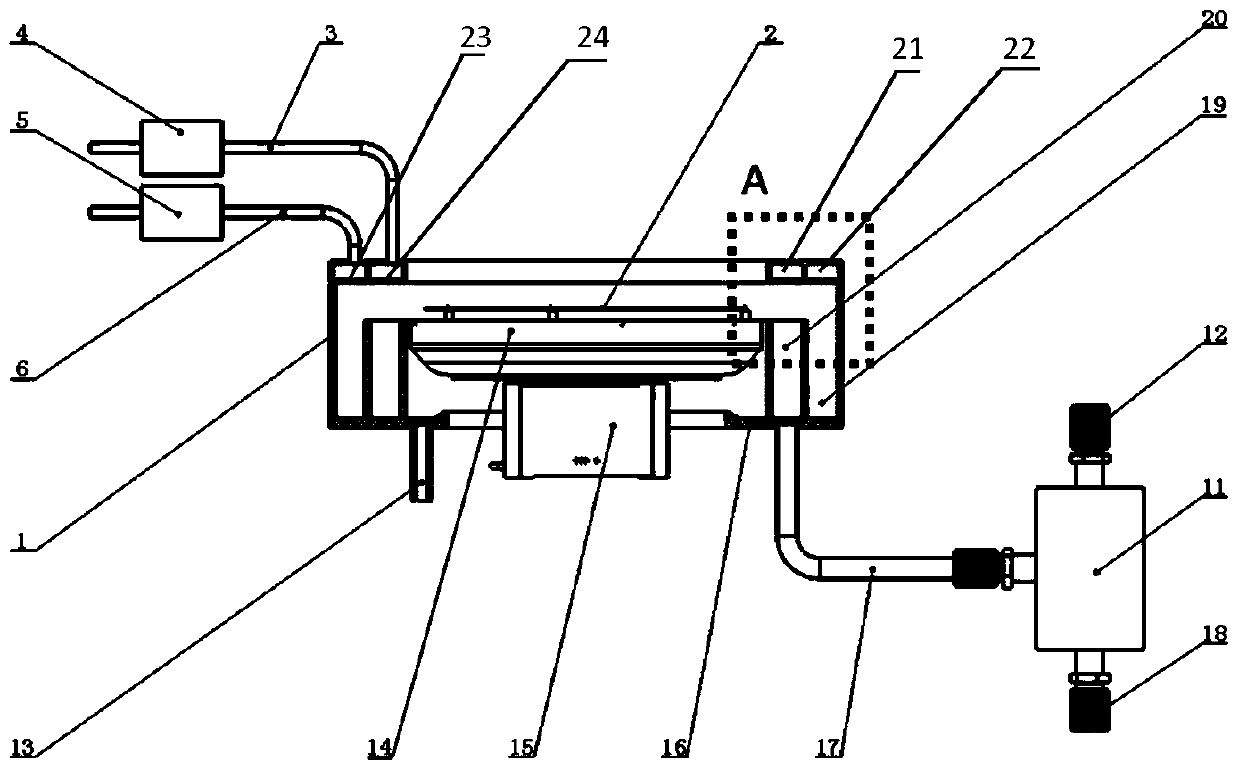
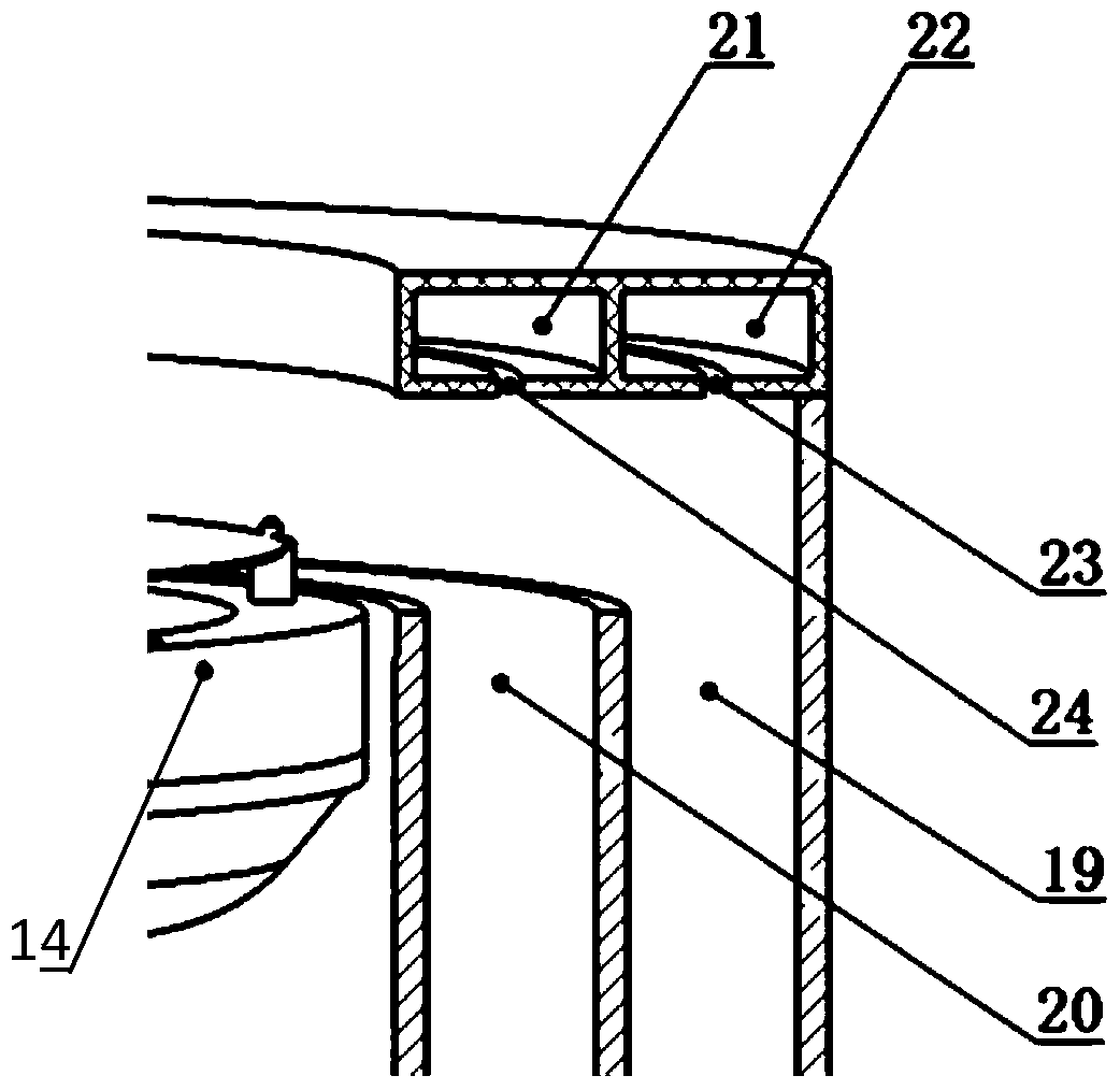
[0032] The cleaning liquid collecting device of the present invention can use the gas curtain formed by the gas to change the moving direction of the cleaning liquid so that it enters the cleaning liquid collecting structure, and is finally separated and recovered in the gas-liquid separation device. In the following specific embodiments of the prese...


PUM


Abstract

The invention discloses a cleaning liquid collecting device comprising an air inflow portion, a cleaning liquid collecting portion, and an air-liquid separating portion. The air inflow portion supplies air to the cleaning liquid collecting portion. An annular air curtain is formed at an air outlet and achieves inelastic collision with cleaning liquid separated from the surface of a wafer. Thus, the cleaning liquid is changed in moving direction, enters an air-liquid collecting cavity and is separated and exhausted by the air-liquid separating portion. The cleaning liquid collecting device may reduce back-splash of cleaning medium at the sidewall of a cleaning liquid collecting structure, prevents secondary pollution, and improves liquid cleaning medium recovery efficiency.

Description

technical field [0001] The invention relates to the field of semiconductor cleaning equipment, in particular to a cleaning liquid collection device. Background technique [0002] In recent years, with the continuous shrinking of the feature size of integrated circuits, the requirements for the wafer cleaning process are also getting higher and higher. Cleaning equipment has also developed from the initial tank cleaning to more complex and precise single-chip cleaning. In the process of single-wafer cleaning, the rotating body of the cleaning equipment drives the wafer to rotate, and the cleaning liquid or ultrapure water on the surface of the wafer can be thrown out for recycling or discharge. [0003] Generally speaking, a liquid collecting structure is arranged around the rotating body of the cleaning device. When the cleaning medium is thrown from the surface of the wafer under the action of rotating centrifugal force and touches the side wall of the liquid collection s...

Claims


Application Information

Patent Timeline
Patent Type & Authority Patents(China)
IPC IPC(8): H01L21/67H01L21/02
CPCH01L21/02041H01L21/67017
Inventor 滕宇吴仪李伟
Owner BEIJING SEVENSTAR ELECTRONICS CO LTD
Why Eureka
Try Eureka