
Industrialized regeneration method of SCR plate-type denitration catalyst

A denitrification catalyst and catalyst technology, applied in the field of denitrification catalysts, can solve problems such as deactivation and failure to restore initial activity

Inactive Publication Date: 2015-12-23
WUHAN IRON & STEEL ENG TECH GROUP
View PDF8 Cites 8 Cited by
  • Summary
  • Abstract
  • Description
  • Claims
  • Application Information

AI Technical Summary

Problems solved by technology

Although on-site regeneration may temporarily restore a certain activity of the catalyst, because the poisoning substances are not fundamentally removed, it is easy to fail to restore the initial activity and deactivate again in a short period of time

Method used


Image

  • Industrialized regeneration method of SCR plate-type denitration catalyst

Examples


Embodiment 1

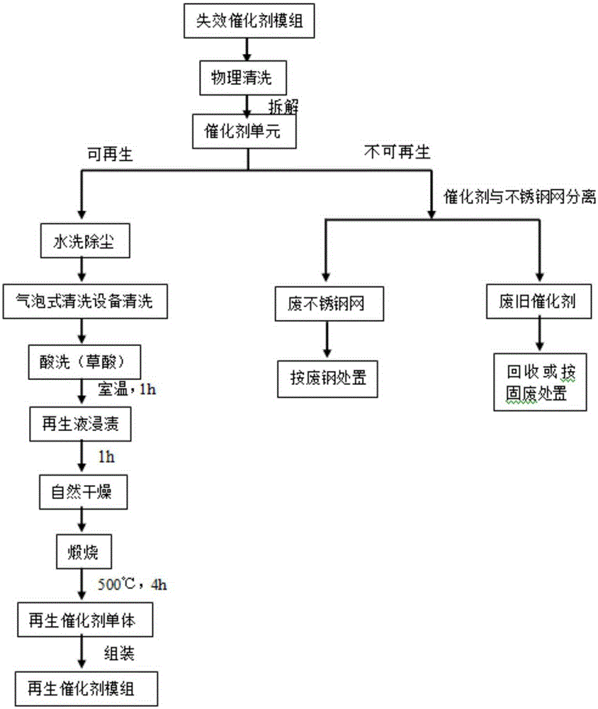
[0025] Embodiment 1 of the present invention provides a factory regeneration method for an SCR plate denitration catalyst.

[0026] see figure 1 , The regeneration of deactivated SCR denitrification catalyst mainly includes several steps: physical cleaning→catalyst module disassembly→catalyst unit (single box catalyst)→regeneration analysis→renewable catalyst dedusting (water washing dedusting and bubble cleaning equipment cleaning dedusting)→ Pickling → impregnation in regeneration solution → dryingcalcinationassembly into a catalyst module.

[0027] (1) Physical cleaning: The main purpose of physical cleaning is to sweep away impurities such as floating dust attached to the surface of the catalyst. The catalyst module is placed in a special purge bed, blown with compressed air, and the blown dust is collected in the ash hopper for centralized treatment.

[0028] (2) Regeneration analysis: The deactivation of the catalyst caused by thermal sintering and mechanical ero...


PUM


Abstract

The invention discloses an industrialized regeneration method of an SCR plate-type denitration catalyst. According to the technical scheme, an invalid SCR plate-type denitration catalyst module is disassembled into a catalyst unit to perform regeneration disposal. The invalid old catalyst module is recovered and disassembled, and regeneration disposal is performed with a single-box catalyst as a unit, so that the activity and denitration efficiency of an old catalyst are recovered, the catalyst unit is re-assembled into a catalyst module, and then the catalyst module is put into use.

Description

technical field [0001] The invention relates to the field of denitration catalysts, in particular to a regeneration method for an SCR plate-type denitration catalyst. Background technique [0002] During the "Twelfth Five-Year Plan" period, the domestic denitrification market has achieved explosive growth. According to relevant national policies, by 2015, nearly 600 million MW of power plant boiler denitrification work will be completed, and the explosive denitrification field will form a total of 1100. The huge market of 100 million yuan, the related denitrification technology - SCR process is widely used. [0003] The SCR denitrification catalyst currently used in coal-fired power plants is directly installed between the boiler economizer and the air preheater in a high-dust arrangement. As time goes on, the high concentration of dust in the flue gas will wash the catalyst surface and cause it to block or poisoning, the activity of the catalyst will gradually decrease. W...

Claims


Application Information

Patent Timeline
Patent Type & Authority Applications(China)
IPC IPC(8): B01J38/00B01J38/62B01J38/48B01J38/02B01J38/68
Inventor 柳子云何知棋王俊尧朱万卿李娟
Owner WUHAN IRON & STEEL ENG TECH GROUP
Learn More