Multi-channel liquid transfer device

A transfer device and multi-channel technology, applied in the field of biomedicine, can solve the problems of time-consuming and laborious manual operation, and achieve the effects of convenient operation, simple structure and easy integration

Inactive Publication Date: 2015-12-23
SOUTHEAST UNIV
View PDF5 Cites 7 Cited by
  • Summary
  • Abstract
  • Description
  • Claims
  • Application Information

AI Technical Summary

Problems solved by technology

However, for the CDC, which needs to process a large number of samples, manual operation is time-consuming and laborious.
Moreover, during the pipetting process, it is necessary to load the pipette tip, discard the pipette tip, etc.

Method used


Image

  • Multi-channel liquid transfer device
  • Multi-channel liquid transfer device
  • Multi-channel liquid transfer device

Examples


Embodiment Construction

[0017] The present invention will be further described below in conjunction with the accompanying drawings.

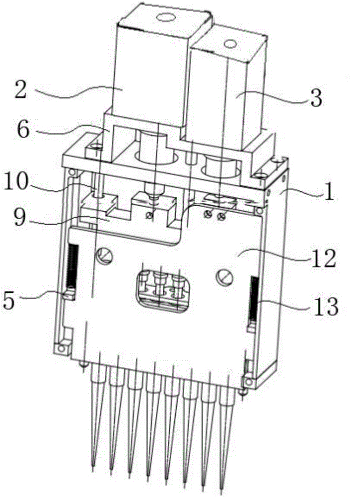
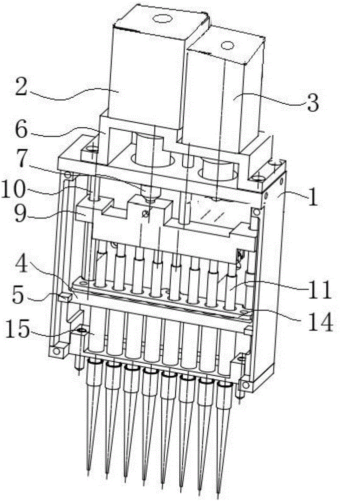
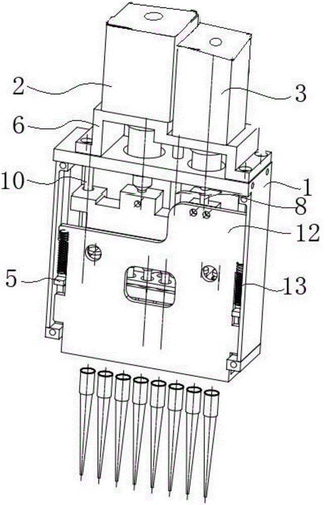
[0018] Such as figure 1 , 2 As shown in , 3, a multi-channel liquid transfer device includes a housing 1 with a front opening, and the housing 1 is processed from a monolithic metal piece; a first drive motor 2 is fixed on the top of the housing 1 through a motor bracket 6 The first transmission screw rod 7 of the first drive motor 2 passes through the top of the casing and is connected to the slider 9 arranged in the casing. A vertical guide post 10 is respectively arranged on the inside of the casing 1 close to the two side walls. Block 9 two ends perforate pass vertical guide post, make slide block keep horizontal state when moving up and down. Eight piston rods 11 with pistons are evenly arranged on the bottom of the slider 9 . Specifically, the middle of the slider 9 protrudes downwards, and the bottom of the protruding end is provided with a plurality of slots...


PUM


Abstract

The invention relates to a multi-channel liquid transfer device which comprises a shell, a liquid sucking and discharging assembly and a liquid stirring and sucking head assembly. A first drive motor of the liquid sucking and discharging assembly drives a first transmission lead screw to move up and down to drive a sliding block and a piston rod to move up and down, and liquid sucking, discharging, blowing, stirring and uniform mixing operation is achieved; a second drive motor of the liquid stirring and sucking head assembly drives a second transmission lead screw to move downwards to compress a spring, an L-shaped movable plate is pushed to move downwards, and the side face, located below the bottom wall of the shell, of the L-shaped movable plate exerts downward pushing force on a liquid sucking head, so that the liquid sucking head arranged at the bottom of a small-diameter cylinder in a sleeving mode falls off; then, the second drive motor controls the second transmission lead screw to move upwards, and meanwhile, the compressed spring exerts upward elastic force on the L-shaped movable plate, so that the L-shaped movable plate moves upwards and returns to the position where the L-shaped movable plate makes contact with the second transmission lead screw. The multi-channel liquid transfer device is simple in structure, the whole device is matched with an external mechanical arm for driving, and the operation such as installation of the liquid sucking head, liquid transfer and liquid sucking head discarding can be efficiently and accurately achieved in an automatic liquid treatment work station.

Description

technical field [0001] The invention relates to the technical field of biomedicine, in particular to a multi-channel liquid transfer device. Background technique [0002] Liquid pipetting devices are widely used in the processing of biochemical samples in the fields of disease control, food safety, forensic identification, and genomics. At present, the main adaptation in biochemical laboratories is a single pipette, and manual operation completes the liquid transfer process. But for the CDC, which needs to process a large number of samples, manual operation is time-consuming and laborious. Moreover, during the pipetting process, it is necessary to load the pipette tip, discard the pipette tip, and other operations. Therefore, a multi-channel, easy-to-integrate and automated device is required to complete the pipetting process in disease sample screening. Contents of the invention [0003] The purpose of the present invention is to provide a multi-channel liquid transfer...

Claims


Application Information

Patent Timeline
Patent Type & Authority Applications(China)
IPC IPC(8): B01L3/02
Inventor 何农跃邬燕琪陈慧
Owner SOUTHEAST UNIV
Why Eureka
Try Eureka