

Sand plating solution device on diamond cutting line
A technology of diamond cutting wire and plating solution, which is applied in the direction of electrolytic coating, coating, etc., can solve the problems of high waste wire rate, affect product quality, and reduce work efficiency, so as to reduce production costs, solve uneven sanding, and improve The effect of product quality
- Summary
- Abstract
- Description
- Claims
- Application Information
AI Technical Summary
Problems solved by technology
Method used
Image

Examples
Embodiment 1
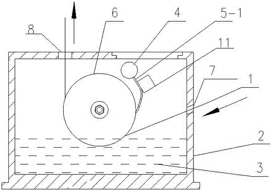
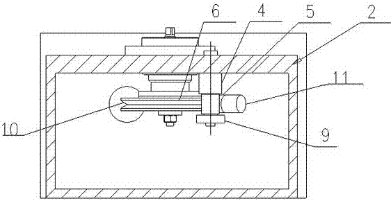
[0025] Embodiment 1: sand plating solution device on the diamond cutting line, such as figure 1 and figure 2 As shown, including the effusion box 2, the side wall of the effusion box 2 is provided with an inlet hole 7, the upper part of the effusion box 2 is provided with an outlet hole 8, and the side wall of the effusion box 2 is provided with a lead wheel 6, and the lead wire The wheel 6 is provided with a V-shaped groove 10 for the diamond cutting wire 1 to pass through, and a cleaning device is provided on the side wall of the liquid accumulation tank 2. The cleaning device is located on the side of the wire wheel 6 in the direction of the diamond cutting wire 1. Cleaning The device includes a scraper 5-1 and a fixed shaft 4, one end of the fixed shaft 4 is arranged on the side wall of the liquid accumulation tank 2, the lead wheel 6 and the fixed shaft 4 are arranged on the same side wall of the liquid accumulation tank 2, and the scraper 5-1 The upper end is connected...
Embodiment 2
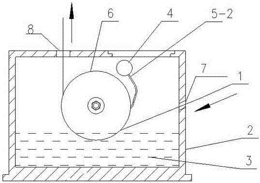
[0027] Embodiment 2: sand plating solution device on the diamond cutting line, such as image 3 As shown, the scraper 5-2 is an elastic plate, and the others are the same as in Embodiment 1.
[0028] Working process: fine-tune the lead wheel 6 first, and then apply sand plating solution.
[0029] The process of fine-tuning the lead wheel 6 to the left and right along the long hole: unscrew the fastening screw 18, and adjust the bearing sleeve assembly 12 to the left and right along the long hole 15, so that the bearing sleeve assembly 12 and the screw shaft 13 reach the appropriate position on the liquid accumulation tank 2, That is to ensure that the bottom of the lead wheel 6 can be centered with the center of the outlet hole 8 left and right, and the fastening screw 18 can be tightened; Lead wire wheel 6 to the suitable position on screw shaft 13, guarantee that the V-shaped groove bottom of lead wire wheel 6 can be centered front and back with outlet hole 8 center, tighte...
PUM
 Abstract
Description
Claims
Application Information