Gas turbine

A gas turbine, cooling air technology, applied in the cooling of turbine/propulsion device, cooling of engine, engine function, etc., can solve the problems of low performance of gas turbine, axial deviation of bearing box and rotor, etc., and achieve uniform thermal expansion and contraction. , to avoid the effect of axial deviation

Inactive Publication Date: 2015-12-23
MITSUBISHI HITACHIPOWER SYST LTD
View PDF6 Cites 1 Cited by
  • Summary
  • Abstract
  • Description
  • Claims
  • Application Information

AI Technical Summary

Problems solved by technology

Therefore, especially in the struts, due to the difference in the thermal expansion and contraction of each strut in the circumferential direction, the axial deviation of the bearing housing and the rotor occurs, which may lead to contact between the rotating body and the stationary body and the performance of the gas turbine.

Method used


Image

  • Gas turbine
  • Gas turbine
  • Gas turbine

Examples


Embodiment Construction

[0073] Hereinafter, the gas turbine 1 according to the first embodiment of the present invention will be described.

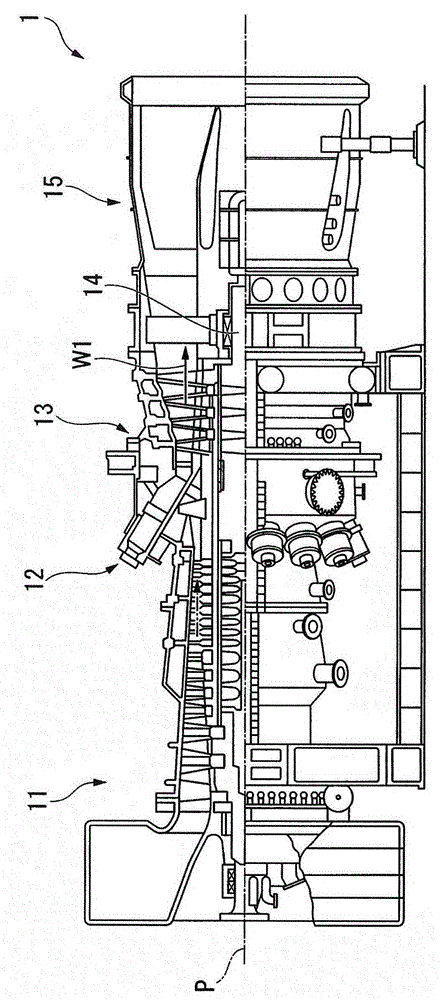
[0074] Such as figure 1 As shown, the gas turbine 1 is configured to mix compressed air generated by a compressor 11 with fuel through a combustor 12 and then combust it to generate high-temperature, high-pressure combustion gas W1. In addition, the gas turbine 1 obtains rotational power by causing the combustion gas W1 to flow into the turbine 13 to rotate the rotor 14 of the turbine 13 around the axis P. Furthermore, the turbine 13 is connected to, for example, an unillustrated generator, and generates electricity by the rotational power.

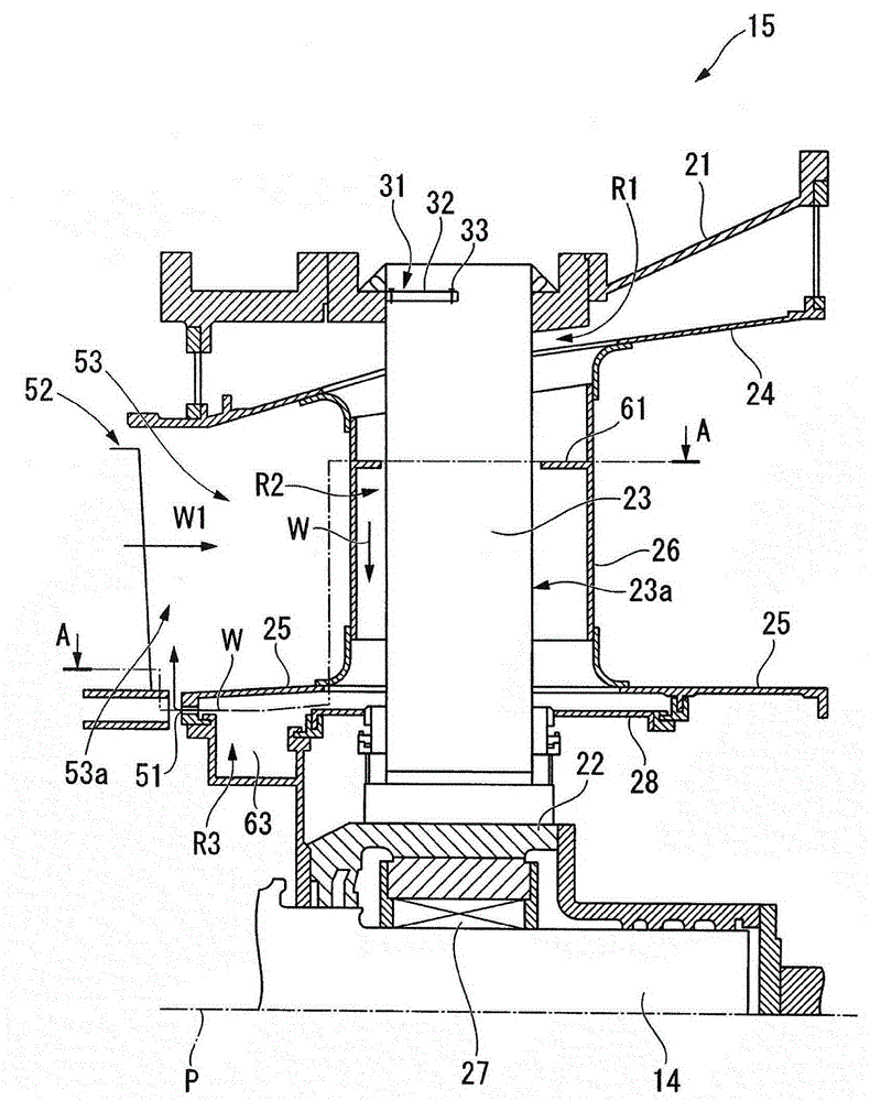
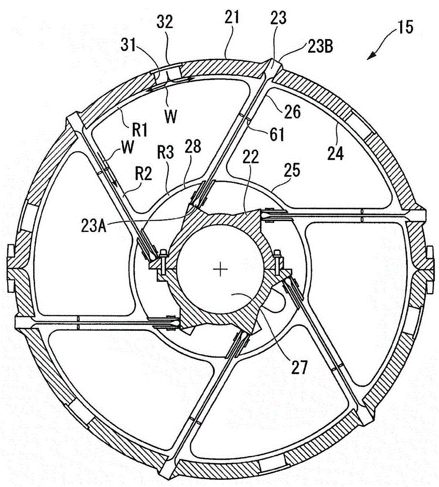
[0075] Then, the combustion gas W1 is exhausted through the exhaust chamber 15 after rotating the turbine 13 .

[0076] It should be noted that, in the following, the compressor 11 side of the gas turbine 1 ( figure 1 The left side of the paper) is referred to as the "upstream side of the axis P direction", and the side...


PUM


Abstract

A gas turbine configured to prevent eccentricity of a rotor (14) due to heat is installed with a strut (23), an outer diffuser (24), an inner diffuser (25), a strut cover (26), and a partition wall (28), wherein the gas turbine includes an inflow hole (31) for cooling air (W), a first flow passage (R1) formed between a casing wall (21) and the outer diffuser (24), a second flow passage (R2) formed between the strut (23) and the strut cover (26), a third flow passage (R3) formed between the inner diffuser (25) and the partition wall (28), and an outflow hole (51) installed in the inner diffuser (25).

Description

[0001] This application is a divisional application of an invention patent application with an application date of May 29, 2012, an application number of 201280001650.7, and an invention title of "gas turbine". technical field [0002] The present invention relates to a gas turbine provided with a cooling structure in an exhaust chamber. [0003] this application claims priority based on Japanese Patent Application No. 2011-197076 for which it applied to Japan on September 9, 2011, and uses the content here. Background technique [0004] The gas turbine generates high-temperature and high-pressure combustion gas by supplying and combusting fuel gas and compressed air into the combustor, and drives the turbine with the combustion gas to generate rotational power. Then, the combustion gas driven by the turbine is converted into a static pressure by the diffuser in the exhaust chamber, and released to the atmosphere. [0005] In such a gas turbine, the temperature of the combu...

Claims


Application Information

Patent Timeline
Patent Type & Authority Applications(China)
IPC IPC(8): F01D25/30F01D25/24F02C7/18
CPCF01D9/065F01D25/12F01D25/14F01D25/162F01D25/30F05D2230/54F05D2250/314F05D2260/607F01D25/16F01D25/24F02C7/18
Inventor 桥本真也
Owner MITSUBISHI HITACHIPOWER SYST LTD
Why Eureka
Try Eureka