
Large-aperture curved surface optical element micro-defect detection and laser restoration apparatus

A technology for optical components and laser repair, which is applied in the direction of optical testing for flaws/defects, measuring devices, and material analysis through optical means. It can solve problems such as low positioning accuracy and slow detection speed, and achieve improved service life and rapid detection. And the effect of precise positioning and compact structure design

Active Publication Date: 2015-12-23
HARBIN INST OF TECH +1
View PDF6 Cites 16 Cited by
  • Summary
  • Abstract
  • Description
  • Claims
  • Application Information

AI Technical Summary

Problems solved by technology

[0004] The present invention aims to solve the problems of slow detection speed and low positioning accuracy of micro-defects of large-diameter fused silica optical elements, and realize that laser pretreatment and laser repair can be performed on the surface of fused silica optical elements at different stations on the same platform. A detection and laser repair device for micro-defects on the surface of large-aperture curved optical components

Method used


Image

  • Large-aperture curved surface optical element micro-defect detection and laser restoration apparatus
  • Large-aperture curved surface optical element micro-defect detection and laser restoration apparatus
  • Large-aperture curved surface optical element micro-defect detection and laser restoration apparatus

Examples


specific Embodiment approach 1

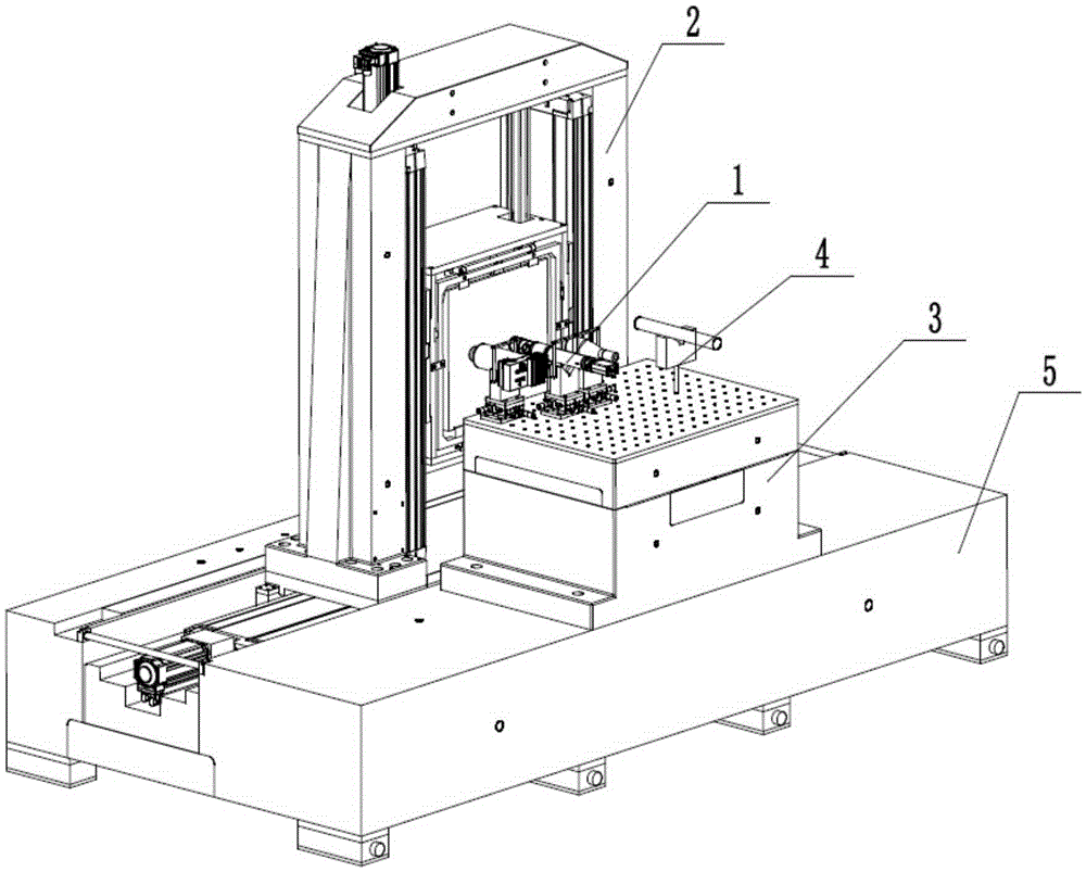
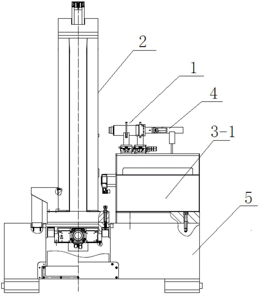
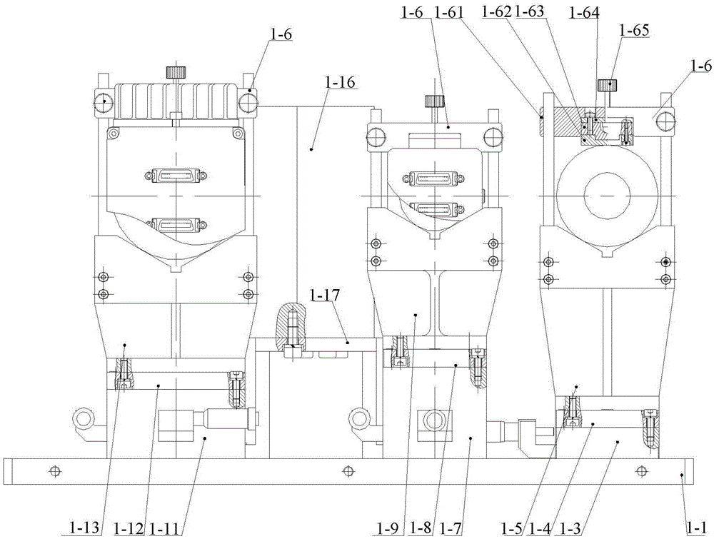
[0044] Specific implementation mode 1. Combination Figure 1 to Figure 8 Describe this embodiment, a detection and laser repair device for micro-defects on the surface of a large-diameter curved optical element described in this embodiment, which includes a micro-detection unit 1 that can be fine-tuned, a two-dimensional large-stroke rapid movement device 2, and a Z-axis motion Device 3, laser component 4 and carrying platform 5;

[0045] The fine-tunable microscopic detection unit 1, the two-dimensional large-stroke fast moving device 2, the Z-axis motion device 3 and the laser assembly 4 are all arranged on the carrying platform 5, and the upper surface of the carrying platform 5 is provided with grooves along the X-axis direction , the two-dimensional large-stroke fast moving device 2 is set in the groove of the carrier table 5,

[0046] The fine-tunable microscopic detection unit 1 and the laser assembly 4 are both arranged on the platform of the Z-axis movement device 3,...

specific Embodiment approach 2

[0073] Specific Embodiment 2. This embodiment is a further description of the detection and laser repair device for micro-defects on the surface of a large-diameter curved optical element described in Specific Embodiment 1. The X-axis motion unit also includes a sheet metal box cover 2 -5. The lower slot 2-6 of the sheet metal box and the outlet box 2-7;

[0074] The lower slot 2-6 of the sheet metal box is fixed on both sides of the X-axis moving guide rail 2-2, and the upper cover 2-5 of the sheet metal box is buckled on the X-axis moving guide rail 2-2 and the lower slot 2-6 of the sheet metal box On the top, between the upper cover 2-5 of the sheet metal box and the lower slot 2-6 of the sheet metal box is a wire slot, the outlet box 2-7 is arranged on one side of the X-axis moving guide rail 2-2, and the outlet box 2- The outlet of 7 is aligned with the wire slot.

[0075] The sheet metal box upper cover 2-5, the sheet metal box lower groove 2-6 and the outlet box 2-7 de...

specific Embodiment approach 3

[0076] Specific Embodiment 3. This embodiment is a further description of the detection and laser repair device for micro-defects on the surface of a large-diameter curved optical element described in Embodiment 1 or 2. Limiting blocks are provided on the carrying frame 2-9. , the limit block is fixed on the upper side of the lower frame plate of the bearing frame body 2-9.

[0077] The limit block described in this embodiment is used to adjust and fix the position of the optical device.


PUM


Abstract

The invention relates to an optical element micro-defect detection and laser restoration apparatus, and concretely relates to a large-aperture curved surface optical element micro-defect detection and laser restoration apparatus. The problems of low detection speed and low positioning accuracy of micro-defects of a large-aperture fused quartz optical element are solved. A fine-tunable microscopic detection unit, a two-dimensional long-travel fast movement device, a Z-axial movement device and a laser assembly are arranged on a supporting desk, a groove is arranged on the upper surface of the supporting desk along an X-axial direction, the two-dimensional long-travel fast movement device is arranged in the groove of the supporting desk, the fine-tunable microscopic detection unit and the laser assembly are arranged on the platform of the Z-axial movement device, and the axis directions of the fine-tunable microscopic detection unit and the laser assembly are respectively vertical to the side surface of the two-dimensional long-travel fast movement device. The apparatus is suitable for being used in large-aperture curved surface optical element micro-defect detection and laser restoration.

Description

technical field [0001] The invention relates to a detection and laser repairing device for micro-defects on the surface of an optical element. Background technique [0002] With the depletion of fossil energy, nuclear fusion energy has become the most ideal future energy for human beings due to its inexhaustible and clean advantages. In the statistics of the terminal optical components of each device, fused silica optical components occupy a large part and are one of the most commonly used optical materials in high-power solid-state laser systems. Fused silica optical components are hard and brittle materials that are prone to microcracks during cold clamping. In a high-power solid-state laser system, the fused silica optical element is irradiated by a triple-frequency intense laser, which is prone to laser damage, forming micro-cracks, micro-pits and other ablation point micro-defects. When micro-defects such as micro-cracks or ablation points appear, the light-transmitti...

Claims


Application Information

Patent Timeline
IPC IPC(8): G01N21/01G01N21/95
Inventor 陈明君赵林杰廖然郑万国李省伟袁晓东廖威
Owner HARBIN INST OF TECH
Learn More