Non-contact ultrasonic flow velocity meter and non-contact flow velocity detection method

A non-contact, ultrasonic technology, used in fluid velocity measurement, velocity/acceleration/impact measurement, measurement devices, etc., can solve the problems of difficult manufacturing and transportation, low installation position accuracy, inconvenient debugging and maintenance, etc., to improve stability. The effect of stability and accuracy, low relative position accuracy, convenient debugging and maintenance

Inactive Publication Date: 2015-12-23
TIANJIN ZHONGZHONG SCI & TECH CO LTD
View PDF3 Cites 14 Cited by
  • Summary
  • Abstract
  • Description
  • Claims
  • Application Information

AI Technical Summary

Problems solved by technology

[0002] The current industrial flow measurement generally has the problem of large pipe diameter and large flow measurement difficulty. This is because the general flowmeter will bring difficulties in manufacturing and transportation with the increase of the measurement pipe diameter, increase the cost, increase the energy loss, The disadvantages of inconvenient installation
Since the existing ultrasonic flowmeter needs to install probes at different depths in the measurement of river channels and open channels, it leads to inconvenient installation, low accuracy of installation position, inconvenient debugging and maintenance, and large measurement errors.

Method used


Image

  • Non-contact ultrasonic flow velocity meter and non-contact flow velocity detection method
  • Non-contact ultrasonic flow velocity meter and non-contact flow velocity detection method
  • Non-contact ultrasonic flow velocity meter and non-contact flow velocity detection method

Examples


Embodiment 1

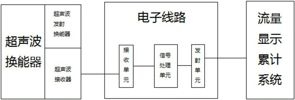
[0039] In this embodiment, preferably, the ultrasonic transducer is a piezoelectric transducer, the ultrasonic transmitting transducer adopts the inverse piezoelectric effect, and the ultrasonic receiver adopts the piezoelectric effect. The piezoelectric transducer utilizes the piezoelectric effect of the piezoelectric material, and uses a suitable transmitting circuit to add electric energy to the piezoelectric element of the ultrasonic transmitting transducer to generate ultrasonic vibration. Ultrasonic waves are injected into the fluid at a certain angle, then received by the ultrasonic receiver, and converted into electrical energy by piezoelectric elements for detection.

[0040] Preferably, in this embodiment, the piezoelectric transducer is made of lead zirconate titanate.

[0041] In order to ensure the directionality of the vibration, in this embodiment, the ultrasonic transducer is a circular sheet that vibrates along its thickness.

[0042] Further preferably, the ...

Embodiment 2

[0047] The invention also discloses a non-contact flow velocity detection method, comprising the following steps:

[0048] S1: Calculate the average velocity of the water flow: using the velocity area method, the radar water velocity meter detects the velocity of the water surface and transmits it to the host computer, calculates the velocity correction coefficient K, measures the horizontal average velocity, and obtains the water flow section through the data provided by the liquid level gauge area, and finally calculate the flow rate and send it to the signal processing unit;

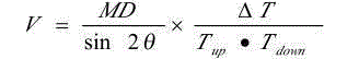
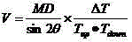
[0049]S2: Install the ultrasonic transducer: attach the ultrasonic transmitting transducer and the ultrasonic receiver to the outer wall of the pipeline to be tested at a certain distance, using the V method of two sound paths, the W method of four sound paths, or the use of sound waves Directly pass through the relative installation Z method of the pipeline under test, record the propagation time of ...


PUM


Abstract

The invention discloses a non-contact ultrasonic flow velocity meter. The non-contact ultrasonic flow velocity meter comprises an ultrasonic transducer, an electronic circuit and a flow display and accumulation system, wherein the ultrasonic transducer comprises an ultrasonic emission transducer and an ultrasonic receiver; the ultrasonic emission transducer is used for converting electric energy into ultrasonic energy, and emitting the ultrasonic energy to the detected flow; the ultrasonic receiver is used for receiving ultrasonic signals and sending the ultrasonic signals to the electronic circuit; the electronic circuit comprises an emission unit, a receiving unit and a signal processing unit; the receiving unit is used for receiving the ultrasonic signals sent from the ultrasonic receiver and sending the ultrasonic signals to the signal processing unit to process the signals; and the emission unit sends the signals processed by the signal processing unit to the flow display and accumulation system. As the non-contact ultrasonic flow velocity meter installs the ultrasonic emission transducer and the ultrasonic receiver on the outer wall of a pipeline to be detected, flow detection when the water flow is opened wide can be performed, and no detection elements are required to be installed in the flow while the flowing state of the flow is not changed.

Description

technical field [0001] The invention relates to a non-contact ultrasonic water flow velocity meter and a non-contact flow velocity detection method. Background technique [0002] The current industrial flow measurement generally has the problem of large pipe diameter and large flow measurement difficulty. This is because the general flowmeter will bring difficulties in manufacturing and transportation with the increase of the measurement pipe diameter, increase the cost, increase the energy loss, These disadvantages are inconvenient to install. Since the existing ultrasonic flowmeter needs to install probes at different depths in the measurement of rivers and open channels, it leads to inconvenient installation, low accuracy of installation position, inconvenient debugging and maintenance, and large measurement errors. Contents of the invention [0003] The purpose of the present invention is to provide a non-contact ultrasonic water flow velocity meter and a non-contact ...

Claims


Application Information

Patent Timeline
Patent Type & Authority Applications(China)
IPC IPC(8): G01P5/24
Inventor 刘新刚
Owner TIANJIN ZHONGZHONG SCI & TECH CO LTD
Why Eureka
Try Eureka