Ultrahigh voltage DC arrester state detection device with Hall sensor acting as framework

A Hall sensor and UHV DC technology, which is applied in the direction of measuring devices, instruments, and measuring electrical variables, etc., can solve problems such as the inability to stabilize and accurately detect the leakage current of UHV DC arresters, and achieve simple structure, improved withstand voltage, and The effect of strong self-healing and self-adaptive ability

Active Publication Date: 2015-12-23
RED PHASE INC
View PDF15 Cites 7 Cited by
  • Summary
  • Abstract
  • Description
  • Claims
  • Application Information

AI Technical Summary

Problems solved by technology

[0008] The invention provides a device for detecting the state of an UHV DC arrester based on a Hall sensor, the main purpose of which is to overcome the defect that the existing leakage current alarm system cannot stably and accurately detect the leakage current of an UHV DC arrester

Method used


Image

  • Ultrahigh voltage DC arrester state detection device with Hall sensor acting as framework
  • Ultrahigh voltage DC arrester state detection device with Hall sensor acting as framework
  • Ultrahigh voltage DC arrester state detection device with Hall sensor acting as framework

Examples


Embodiment 1

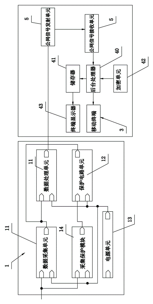
[0036] refer to figure 1 . An online detection system for the leakage current of a UHV DC arrester, comprising a detection device 1 arranged near the DC arrester, a data sending device for transmitting the detection result of the leakage current obtained by the detection device 1, a data receiving device, Central monitoring device and mobile terminal 3. The data sending device is a public network signal transmitting unit 5 , and the data receiving device is a public network signal receiving unit 6 . The public network signal transmitting unit 5 and the public network signal receiving unit 6 can realize data transmission through the mobile public network (GSM network or GPRS network). The transmitting unit 5 is preferably a communication module of a GSM network or a GPRS network. The central monitoring device includes a background processor 40 and a storage device 41, the input end of the background processor 40 is connected to the data receiving device, and the output end o...

Embodiment 2

[0060] refer to Figure 6 . This embodiment is substantially the same as the implementation of Embodiment 1, the difference is that: the data sending device includes a radio frequency signal transmitting unit 50, a frequency modulation forwarding unit 51 and a dual-mode communication unit 52 connected in sequence, and the data receiving The device is the public network signal receiving unit 6 connected to the output end of the dual-mode communication unit 52 .

[0061] Adopting the above settings can make this embodiment not only transmit the circuit detection value to the central monitoring device in the range covered by the public network, but also pass the radio frequency signal transmitting unit and the frequency modulation forwarding unit in the area where there is no public network signal. In cooperation, the lightning strike information is first sent to a dual-mode communication unit set within the coverage of the public network, and then transmitted to the central mon...


PUM


Abstract

The invention provides an ultrahigh voltage DC arrester state detection device with a Hall sensor acting as a framework. The ultrahigh voltage DC arrester state detection device comprises a data acquisition unit, a data processing unit, a protection circuit unit and a power supply unit. The data acquisition unit comprises a current sensor, a power amplifier and a circuit acquisition module. The current sensor comprises an annular shell, a magnetic core which is arranged in a C shape, and two Hall circuit modules. A first coil winding and a second coil winding are respectively wound on the magnetic core, and the magnetic core is installed in an accommodating space. An electrical bridge is connected between the two Hall circuit modules. The magnetic flux density direction generated by the second coil winding is opposite to the magnetic flux density direction of the first coil winding. Double Hall circuit modules are adopted to acquire arrester leakage current so that nonlinearity and position error of the sensor can be greatly reduced, and anti-interference capability and the scope of measuring range of the sensor can be enhanced.

Description

technical field [0001] The invention relates to a state detection technology of an ultra-high voltage direct current circuit arrester, in particular to a device for detecting the state of an ultra-high voltage direct current arrester with a Hall sensor as a framework. Background technique [0002] With the rapid development of my country's economy, the demand for electricity is growing rapidly. However, my country has the natural characteristics that the distribution of power resources does not match the load center area. It is necessary to use long-distance and large-capacity transmission lines to improve the contradiction between power supply and demand. "West to East Power Transmission", Projects such as "North-South Mutual Supply" are the main deployment schemes at this stage, and UHV DC transmission technology is the specific implementation technical means. [0003] DC power transmission converts AC power into DC power through a converter, then sends it to the power rece...

Claims


Application Information

Patent Timeline
Patent Type & Authority Applications(China)
IPC IPC(8): G01R19/00
Inventor 邓敏袁愿林力辉
Owner RED PHASE INC
Why Eureka
Try Eureka