Self-power distributed wireless current sensor

A current sensor, distributed technology, applied in current collectors, battery circuit devices, instruments, etc., can solve the problem of current sensors occupying additional space for separate power supply, and achieves the effect of saving wiring space, compact structure, and high sensitivity

Active Publication Date: 2015-12-23
WUHAN XINGHUI ELECTRIC POWER TECH CO LTD
View PDF9 Cites 9 Cited by
  • Summary
  • Abstract
  • Description
  • Claims
  • Application Information

AI Technical Summary

Problems solved by technology

[0004] The invention provides a self-powered distributed wireless current sensor, which can overcome the defects of existing current sensors that occupy extra space and supply power alone, and realize functions such as self-power supply, wireless transmission, and measurement of multi-phase circuit current.

Method used


Image

  • Self-power distributed wireless current sensor
  • Self-power distributed wireless current sensor
  • Self-power distributed wireless current sensor

Examples


Embodiment

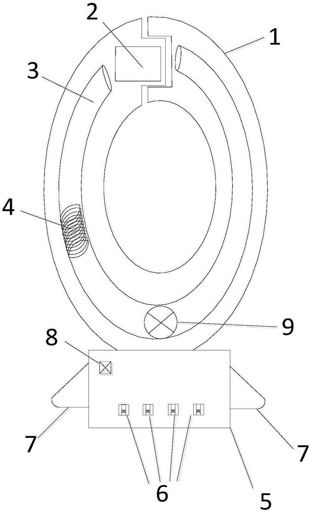
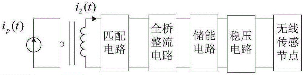
[0044] A self-powered distributed wireless current sensor, which is mainly buckled on the outside of the three-phase wires. When the wires are connected and current flows through, the energy harvesting coil 4 starts to work. The working principle of the energy harvesting coil 4 is similar to that of a transformer, but there are differences. The transformer uses the principle of mutual inductance of the coil to change the AC voltage of the front stage. The primary side of the energy-taking coil 4 is controlled by alternating current rather than voltage, and the primary side is a single-turn winding, and the secondary side is a multi-turn winding. , when the primary side is fed with a sinusoidal alternating current, the voltage induced by the secondary side of the energy-taking coil 4 is sorted out as follows: E = 4.44 2 fN 2 μSI μ / l ...


PUM


Abstract

Provided is a self-power distributed wireless current sensor, comprising pincerlike housings; the pincerlike opening of one pincerlike housing is provided with a Hall element; a magnetic core is arranged in the pincerlike housings and is winded by an energy extraction coil. A control box is arranged under the pincerlike housings, and is internally provided with a power supply management circuit, a signal conditioning circuit, an A/D conversion module, an MCU processor module, and a wireless transmit-receive module. The energy extraction coil is in connection with the power management circuit which is in connection with the signal conditioning circuit; the signal conditioning circuit is in connection with the A/D conversion module; the A/D conversion module is in connection with the MCU processor module; the MCU processor module is in connection with the wireless transmit-receive module. The wireless transmit-receive module can be in wireless communication with a telecommunication device. The self-power distributed wireless current sensor overcomes the deficiencies of additional space occupation and independent power supply of a present current sensor, realizes self power supply, wireless transmission, multiphase circuit current measurement, etc., and can perform many-to-one data transmission.

Description

technical field [0001] The invention relates to a current transformer, in particular to a self-powered distributed wireless current sensor. Background technique [0002] With the rapid growth of power demand and the rapid development of the power system, the power industry is facing serious challenges to increase the utilization rate of power equipment, reduce the operating cost of power equipment, and enhance the safe and stable operation of the power system. Most of the faults in the power system will affect the current, so it is very necessary to monitor the current. my country's electric power construction has entered a new stage of high automation and informationization, and the monitoring of current has also entered a new stage. At present, the environment of many industrial fields and power distribution equipment, especially power distribution switchgear, is relatively complex, and problems such as heating and aging of lines caused by excessive current are likely to ...

Claims


Application Information

Patent Timeline
Patent Type & Authority Applications(China)
IPC IPC(8): G01R19/25H02J7/02G08C17/02
Inventor 黄悦华张迪程江洲袁雪珺曹诗龙
Owner WUHAN XINGHUI ELECTRIC POWER TECH CO LTD
Why Eureka
Try Eureka