
Distribution network cable hybrid direct distribution line fault ranging method based on line side direction traveling wave decomposition

A technology for directional traveling waves and line faults, applied in directions such as fault locations

Active Publication Date: 2015-12-23
KUNMING UNIV OF SCI & TECH
View PDF5 Cites 13 Cited by
  • Summary
  • Abstract
  • Description
  • Claims
  • Application Information

AI Technical Summary

Problems solved by technology

[0003] The purpose of the present invention is to overcome the limitations of the existing fault location method based on line parameter uniformity in the application of cable hybrid line fault location, and propose a hybrid direct distribution line fault based on traveling wave decomposition along the line direction ranging method

Method used


Image

  • Distribution network cable hybrid direct distribution line fault ranging method based on line side direction traveling wave decomposition
  • Distribution network cable hybrid direct distribution line fault ranging method based on line side direction traveling wave decomposition
  • Distribution network cable hybrid direct distribution line fault ranging method based on line side direction traveling wave decomposition

Examples


Embodiment 1

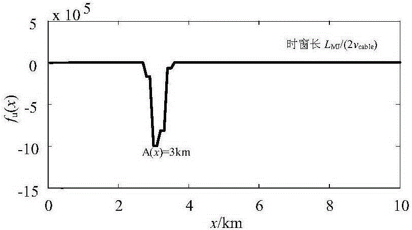
[0055] use as figure 1 The cable-line hybrid direct distribution system is shown, in which, the length of the cable feeder in the cable hybrid line is 10km, the length of the overhead feeder is 10km, the measurement end is located at the beginning of the cable, and the other two healthy lines are cable feeders, the lengths of which are 8km and 10km respectively. 15km. Assume that an AG fault occurs at a distance of 3km from the M terminal within the half-length of the cable MJ, the initial phase angle of the fault is 90°, the transition resistance is 0.01Ω, and the sampling rate is 1MHz.

[0056] Firstly, PCA-SVM is used to identify the fault located in the cable, and then the [k 0 ,k 0 +L MJ / (2v)] and [k 0 +L MJ / (2v),k 0 +L MJ / v] time window, using the line-mode current traveling wave and line-mode voltage traveling wave at the measuring end, the calculation step length along the line is 0.1km, and the length L along the line of the ranging function of the measuring...

Embodiment 2

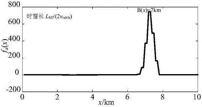
[0058] use as figure 1 The cable-line hybrid direct distribution system is shown, in which, the length of the cable feeder in the cable hybrid line is 10km, the length of the overhead feeder is 10km, the measurement end is located at the beginning of the cable, and the other two healthy lines are cable feeders, the lengths of which are 8km and 10km respectively. 15km. Assume that an AG fault occurs at a distance of 3km from the J node within half the length of the JN line of the overhead line, that is, at a distance of 13km from the M terminal. The initial phase angle of the A phase fault is 90°, the transition resistance is 0.01Ω, and the sampling rate is 1MHz.

[0059] Firstly, PCA-SVM is used to identify the fault located in the overhead line, and then the [k 0 ,k 0 +L JN / (2v)] and [k 0 +L JN / (2v),k 0 +L JN / v] time window, using the line-mode current traveling wave and line-mode voltage traveling wave at the beginning of the overhead line, the calculation step len...


PUM


Abstract

The invention relates to a distribution network cable hybrid direct distribution line fault ranging method based on line side direction traveling wave decomposition, which belongs to the technical field of power system relay protection. When single-phase grounding fault happens to the distribution network cable hybrid direct distribution line, a PCA-SVM is firstly adopted to recognize a line hybrid line fault section; line mode traveling wave is obtained according to fault travelling wave data acquired at a measurement end, the obtained line mode traveling wave is applied and according to line side voltage travelling wave and current travelling wave distribution in a fault region deduced by a Bergeron line transfer equation, the line side voltage travelling wave and the line side current travelling wave are subjected to line side direction traveling wave decomposition, direction travelling wave for line side distribution is acquired, positive travelling wave is used to multiply backward travelling wave, integration is carried out in two sequential time window lengths for building a ranging function, and finally, fault ranging is carried out according to traveling wave mutation distribution of the ranging function along a fault region line length range. After theoretical analysis and the simulation result, the method has good effects.

Description

technical field [0001] The invention relates to a method for fault distance measurement of hybrid direct distribution lines of distribution network cables based on traveling wave decomposition along the line direction, and belongs to the technical field of electric power system relay protection. Background technique [0002] With the continuous development of urban distribution networks, the proportion of cable feeders and cable hybrid lines in the distribution network is increasing. Compared with overhead lines, the cable has its particularity: first, the cable structure is relatively complex, generally composed of a multi-conductor system composed of cable core, shielding layer, sheath, etc.; second, the cable is mostly buried underground, and the relationship with the earth is closer. Due to the tightness, the electromagnetic transient process in the cable is quite different from that of the overhead line, the charging capacitance of the length of the cable grid is large,...

Claims


Application Information

Patent Timeline
IPC IPC(8): G01R31/08
Inventor 束洪春余多田鑫萃高利
Owner KUNMING UNIV OF SCI & TECH
Learn More